Applications and Characteristics Of Overcurrent Relays (ANSI 50, 51)
50/51 and 50/51N relays
Overcurrent relays are the most commonly-used protective relay type. Time-overcurrent relays are available with various timing characteristics to coordinate with other protective devices and to protect specific equipment. Instantaneous overcurrent relays have no inherent time delay and are used for fast short-circuit protection.
Figure 1 below shows the timing characteristics of several typical 51 time-overcurrent relay curve types, along with the 50 instantaneous characteristic.
Figure 1 – ANSI 50 and 51 overcurrent relay characteristics
The pickup level is set by the tap setting, which is usually set in CT secondary amperes but may be set in primary amperes on some microprocessor-based relays.
Each relay curve has a time dial setting which allows the curve to be shifted up or down on the time-current characteristic curve.
In Figure 1, the time dial settings are different to give enough space between the curves to show their differences.
The above are IEEE-standard curves; others are available, depending upon the relay make and model. A solid state electronic or microprocessor-based relay will have all of these curves available on one unit; electromechanical relays must be ordered with a given characteristic that cannot be changed.
The 50 instantaneous function is only provided with a pickup setting. The 30ms delay shown in figure 1 for the 50 function is typical and takes into account both the relay logic operation and the output contact closing time.
Most microprocessor-based units will also have an adjustable delay for the 50 function; when an intentional time delay is added the 50 is referred to as a definite-time overcurrent function. On solid-state electronic and microprocessor-based relays, the 50 function may be enabled or disabled.
On electromechanical relays, the 50 function can be added as an instantaneous attachment to a 51 time-overcurrent relay. If a relay has both 50 and 51 functions present and enabled is referred to as a 50/51 relay.
Typically, overcurrent relays are employed as one per phase. In solidly-grounded medium voltage systems, the most common choice for ground fault protection is to add a fourth relay in the residual connection of the CT’s to monitor the sum of all three phase currents. This relay is referred to as a residual ground overcurrent or 51N (or 50/51N) relay.
The CT arrangement for 50/51 and 50/51N relays for a solidly-grounded system is shown in Figure 2 below.
Figure 2 – Overcurrent relay arrangement with CT’s, including 50/51N
For a low-resistance-grounded system, the use of an overcurrent relay connected to a CT in the service transformer or generator neutral is usually the best option. This CT should have a ratio smaller than the phase CT’s, and the relay pickup range in conjunction with the neutral CT should allow a pickup as low as 10% of the neutral resistor rating.
For a feeder circuit downstream from the service transformer, a zero-sequence CT is recommended, again with a ratio small enough to allow a pickup as low as 10% of the neutral resistor rating.
When an overcurrent relay is utilized with a zero-sequence CT it is referred to as a 50G, 51G or 50/51G relay depending upon relay type used. Figure 3 shows typical arrangements for both these applications.
Figure 3 – Transformer neutral and zero-sequence ground relaying applications for resistance-grounded systems
For ungrounded systems, the ground detection methods are recommended since little ground current will flow during a single phase-to-ground fault. Low voltage solidly-grounded systems are discussed below.
The typical application of phase and residual neutral ground overcurrent relays in one-line diagram form is shown in figure 4.
Figure 4 – Typical application of overcurrent relays
In Figure 4, the designation 52 is the IEEE Std. C37.2-1996 designation for a circuit breaker.
The phase relays are designated 51 and the residual ground overcurrent relay is designated 51N (both without instantaneous function). The bracketed denotes that there are three phase overcurrent relays and three CT’s. The dotted line from the relays to the circuit breaker denotes that the relays are wired to trip the circuit breaker on an overcurrent condition.
Another type of overcurrent relay is the voltage-restrained overcurrent relay 51 V and the voltage-controlled relay 51C. Both are used in generator applications to allow the relay to be set below the generator full-load current due to the fact that the fault contribution from a generator will decay to a value less than the full-load current of the generator.
The 51C relay does not operate on overcurrent unless the voltage is below a preset value. The 51 V relay pickup current shifts as the voltage changes, allowing it to only respond to overcurrents at reduced voltage. Both require voltage inputs, and thus require voltage transformers for operation.
OverCurrent Protection and Coordination (VIDEO)
Cant see this video? Click here to watch it on Youtube.
Reference: System Protection - Bill Brown, P.E., Square D Engineering Services
Let’s analyse phase-to-earth faults in a single-incomer power system
Detect and isolate…
Power-system protection should detect faults and isolate the faulty parts of the power system while keeping the fault-free parts in operation. Protection units are chosen according to the power-system configuration (parallel operation of generators or transformers, loop or radial power system, neutral earthing arrangement…).
Ok, this time I’ll analyse earth fault protection in a single-incomer power system…
Resistance earthing on the transformer
Earth fault protection units (ANSI 51N) are installed on the feeders, incomer and neutral earthing connection.
Figure 1 – Phase-to-earth fault protection (resistance-earthed neutral at transformer)
Time-based discrimination is used between the different protection units. These units are necessarily different from phase fault protection units since the fault currents are in a different range.
The feeder protection units are set selectively in relation to the incomer protection unit, which is itself set selectively in relation to the neutral earthing protection unit (in accordance with discrimination intervals). The fault current flows through the capacitances of the fault-free feeders and the earthing resistance.
All the fault-free feeder sensors detect capacitive current.
To prevent inadvertent tripping, the protection unit on each feeder is set higher than the feeder’s capacitive current.
fault at 3: the D1 circuit breaker is tripped by the protection unit linked to it,
fault at 4: the A circuit breaker is tripped by the incomer protection unit,
fault at 5: the protection unit on the neutral earthing connection trips circuit breaker H on the transformer primary circuit. (fig. 1).
The protection unit at D must be selective in relation to the downstream protection units: if the delay required for protection A is too long, logic discrimination should be used. The neutral earthing protection unit at H acts as back-up should the incomer protection unit at A fail to trip. The incomer protection unit at A acts as back-up should a feeder protection unit at D fail to trip.
A zero sequence generator is used for resistance-earthing. Earth fault protection units (ANSI 51G) are installed on the feeders, incomer and zero sequence generator.
Figure 2 – Phase-to-earth fault protection (resistance-earthed neutral at busbars)
Time-based discrimination is used between the different protection units. The feeder protection units and incomer protection unit are set selectively in relation to the earthing impedance protection unit. As in the previous case, the protection unit on each feeder is set higher than the feeder’s capacitive current.
In the event of a fault on feeder 1, only the D1 feeder circuit breaker trips. In the event of fault on the busbars 2, only the protection unit on the earthing connection detects the fault. It trips circuit breaker A.
In the event of fault on the transformer secondary circuit 3, the incomer protection units detects the fault. It trips circuit breaker H.
NOTE // when circuit breaker A is open, the transformer secondary circuit neutral is isolated. It may be necessary to protect it by a neutral voltage displacement measurement (ANSI 59N).
The zero sequence generator protection unit acts as back-up should the incomer protection unit at A or a feeder protection unit at D fail to trip. If the condition IsD > 1.3 Ic cannot be satisfied for a feeder, a directional earth fault protection unit may be used to discriminate between fault current and capacitive current.
A fault, regardless of its location, produces current which flows through the capacitance of the fault-free feeders. In industrial power systems, this current is generally weak (a few amperes), allowing operations to carry on while the fault is being tracked.
Time-based discrimination is used between the different protection units. The fault is detected by an insulation monitoring device or a neutral voltage displacement protection unit (ANSI 59N).
When the total capacitive current of a power system is high (in the range of ten amperes), additional measures must be taken to quickly clear the fault. Directional earth fault protection can be used to selectively trip the fault feeder.
This is similar to resistance-earthing at the transformer, but the capacitive currents are negligible compared to the fault current, so the protection function is simpler to implement.
The power system is earthed at the transformer. Faults are detected by a specific directional earth fault protection unit (ANSI 67NC), which monitors the active residual current and recognizes faults during their initial transient phase.
Electrical life (durability) of LV circuit breakers due to the switching operations (photo credit: unilec.net)
Test requirements
According to the standard IEC 947-2, there is actually no defined stipulation regarding the requirements of electrical life of a circuit breaker. The numbers of switching operations which a circuit breaker under no-load, normal load, overload and short-circuit conditions has to make and/or break are stipulated.
These numbers vary between two switchings (O-t-CO) for the rated ultimate short-circuit breaking capacity test and a few thousand purely mechanical operations under no-load condition.
Practical aspect
The electrical life or durability (life of the contact tips) of a circuit breaker, similar to a contactor, depends mainly on the magnitude of the breaking current (neglecting the contact erosion due to bouncing during the making operation, which is kept at a minimum with appropriate constructive measures).
Short Circuit Trip
Lower currents in the range of normal service conditions or overloads in the range of the thermally delayed release mechanism has very little influence on the contact life in comparison with the effect of the short-circuit currents of the order of the breaking capacity. Due to a few high current short-circuits close to the bus bars, the electrical erosion of the contacts could be so high that the circuit breaker may have to be replaced.
However, practical experience shows that the magnitude of the short-circuit currents would be rarely of the order of 50 kA or higher. They usually lie much lower in their amplitudes and the contact erosion is also within reasons.
In the case of a circuit breaker which is already installed, it is not easily visible from outside how many short-circuits it has already interrupted or what the actual amplitudes of the short-circuit currents were and whether the circuit breaker has already reached the end if its electrical life.
In spite of the above, the circuit breaker indicates indirectly when it has reached the end of its useful life. The thermal overload release tends to trip earlier, already at the rated value of the current setting on the scale. Thus the protective function of the device remains fully active right up to the end of its life.
The reason of the early tripping is because of the higher temperature-rise of the current path already at the rated current due to the increased contact resistance of the strongly eroded main contacts. In the long run, it affects the tripping characteristic of the thermal release. Early tripping is the result.
A circuit breaker which can no longer continuously carry its normal rated current indicates that the contact resistance is too high (electrically eroded contacts). They have reached the end of their electrical life and are to be replaced.
In other words, the circuit breaker remains reliable and safe up to the end. A normal operation indicates that the circuit breaker is functionally in order. If there is no early tripping after the breaker is switched on, it signifies that it can interrupt a short-circuit as well.
An Example Of Transformer Overload and Short-Circuit Protection (photo credit: ABB; Mariano Berrogain)
NEC Article 450 // Transformers Vaults
Transformer protection consists of both overload protection and short-circuit protection. Overload protection is usually accomplished via proper selection of the secondary overcurrent protective device.
NEC Article 450 gives specific primary and secondary overcurrent device ratings that may not be exceeded. These vary depending upon the accessibility of the transformer to unqualified persons and the impedance of the transformer. The smallest protective device that allows the rated full-load current of the transformer gives the best practical overcurrent protection.
Increasing the secondary overcurrent device size beyond this may be necessary for short-term overloads or for coordination with downstream devices, but in any case the requirements of NEC Article 450 must be met!
Short-circuit protection involves comparison of the transformer damage curve per IEEE Std. C57.109-1993 with the primary overcurrent device time-current characteristic. In general, the damage curve must be to the right and above the primary overcurrent device characteristic.
Another constraint on the primary overcurrent device is that it must be capable of withstanding the inrush of the transformer without tripping (and without damage for currentlimiting fuses).
Example //
An example time-current characteristic showing protection for a 1000 kVA 13.2 kV Delta:
480 Y/277 V, 5.75%Z dry-type transformer is shown in Figure 1. The transformer is protected with a 65E current-limiting primary fuses and a 1200 A electronic-trip secondary circuit breaker. As can be seen from the figure, the fuses do withstand the inrush without damage since the inrush point is to the left and below the fuse minimum melt curve.
Figure 1 – Example protection for a 1000 kVA, 13.2 kV Delta: 480 Y/277V, 5.75%Z dry-type transformer
The transformer is protected from short-circuits by the primary fuses. The secondary circuit breaker provides overload protection at the full-load current of the transformer. Note that the primary fuse and secondary circuit-breaker characteristics overlap for high fault currents; this is unavoidable and is considered acceptable. Note also that the fuse curve and the transformer damage curve overlap; this is unavoidable but these should overlap at the lowest current possible.
For currents below the fuse/transformer damage curve overlap the secondary circuit breaker must protect the transformer.
The lower the point of overlap, the more likely the fault is an external fault on the load side of the secondary circuit breaker and therefore greater chance the secondary circuit breaker will effectively protect the transformer for faults in this region.
Also note that the transformer damage characteristic is shown twice. Because transformer is a delta-wye transformer, a ground-fault on the secondary side of the transformer will result in only 57.7% of the maximum three-phase primary fault current while one secondary winding experiences the full fault current.
This is illustrated in Figure 2, as well as the corollary for delta-delta transformers.
Figure 2 – Fault-current flow for delta-wye transformer L-N faults and delta-delta transformer L-L faults
The damage characteristic has therefore been shifted to 57.7% of its published value to account for secondary line-to-ground faults. Also, the shifted curve has another, more conservative curve shown; this is the frequent-fault curve and is applicable only to the secondary overcurrent device since faults between the transformer secondary and the secondary overcurrent protective device should not be frequent.
Additional devices, such as thermal overload alarms/relays and sudden-pressure relays, are also available for protection of transformers. These are typically specified with the transformer itself and can provide very good protection. However, even if these devices are installed the primary and secondary overcurrent devices must be coordinated with the transformer as described above.
If differential protection is supplied it is the primary protection for internal faults and will operate before the primary overcurrent device. The primary overcurrent device serves as a backup protective device for internal faults in this case.
Reference: System Protection – Bill Brown, P.E., Square D Engineering Services
This technical article focuses on the widely used miniature circuit breakers rated for 240 V or less. These are smaller and lower-rated versions of industrial-grade molded-case circuit breakers rated for 600 V or less. These miniature breakers, called air circuit breakers, are based on thermal, magnetic, or combined thermal-magnetic principles.
They are now almost exclusively installed in all new residences, small businesses, and offices as well as updates of existing older electrical systems. They are rated for: amperes, voltage, and short-circuit or fault-current interruption.
Miniature circuit breakers perform the dual functions of a switch and a fuse. They can open a circuit for safety or maintenance reasons simply by switching their toggle levers to the OFF position. As substitutes for fuses, they provide automatic circuit protection and need not be replaced after a dangerous overcurrent has passed or a short circuit has been corrected.
Let’s continue this article with following topics important for fully understanding MCBs:
The ampere rating defines the maximum current the circuit breaker can carry without tripping. For typical miniature circuit breakers this rating is 2 to 125 A. In residential applications, single-pole breakers protect 20V branch circuits, and two-pole breakers protect 240V branch circuits.
Miniature circuit breakers mounted on DIN rail
The voltage rating of a circuit breaker can be higher than the circuit voltage, but never lower.
The fault current interruption rating (or short-circuit interrupting rating) is the maximum available fault current that could be expected from the overhead or pad-mounted distribution transformer outside a residence. If the transformer can produce 10,000 A of current, each breaker in the loadcenter should be rated for at least 10,000 A.
While residential breakers have ratings of 10,000, 22,000, 42,000, and 65,000 A, the available fault current for most single-family homes rarely exceeds 10,000 A (10 kA).
Each miniature or branch circuit breaker, as shown in the cutaway view Figure 1 below, includes a bimetal strip or element. When this strip is heated to its threshold temperature, it bends enough to unlatch a mechanism and open the breaker’s electrical contacts.
When the contacts open, the toggle on the circuit breaker automatically switches to the OFF position. This, in turn, opens the branch circuit.
Figure 1 – Internal view of a thermal circuit breaker
These small circuit breakers can be reset manually after they have tripped. As with fuses, the ampere rating of the breaker must match the ampacity of the circuit it protects. These circuit breakers are also called plug-in breakers, because they are connected to the loadcenter by plugging them into the busbar tabs or stabs.
A high quality thermal circuit breaker will open a 10,000 A fault at 240 V AC in 40 to 50 ms, or even faster.
Cant see this video? Click here to watch it on Youtube.
Under simple overload conditions, the deflection of a bimetal thermal sensing element within the circuit breaker causes the circuit to open when a preset temperature threshold is reached. Rising temperature in a bimetal element is caused principally by load current (I2R) heating.
The thermal element also factors in the heating or cooling effects caused by nearby heating or cooling sources (furnaces or air conditioners), as well as changes in the ambient temperature.
The size of the bimetal thermal element and its configuration, shape, and electrical resistivity determine the current capacity of a circuit breaker. The most common element is a “sandwich” of two or three different metals. The low-expansion side, for example, might be Invar, the center might be copper or nickel, and there is a wide choice of metals for the high-expansion side.
Some thermal circuit breakers rated for 5 A or lower contain heater coils adjacent to or in series with the bimetal element. These heater coils compensate for the lower anticipated heating action of a fault in a low-current circuit. They augment element self-heating to maintain the temperature of the thermal element closer to the preset threshold temperature, to speed up the trip response in the presence of overcurrent.
Cant see this video? Click here to watch it on Youtube.
Some miniature thermal circuit breakers also contain a magnetic element to accelerate tripping in the presence of an exceptionally fast rising overload. That condition increases current flow fast enough to create a magnetic field in a small electromagnet or solenoid that pulls in a mechanical linkage to unlatch the contacts and trip the breaker before the bimetal element can respond and deflect.
The basic elements of a thermal-magnetic circuit breaker are shown in the simplified diagram Figure 2.
The normal condition of the circuit breaker is illustrated in Figure 2a. The bimetal element in these breakers responds the same way to overcurrent as the element in a simple thermal breaker. As shown in Figure 2b, the bimetal element deflects in proportion to the heating effect of the current passing through the wire in close proximity to it.
As in thermal breakers, the bimetal element will open a 10,000 A fault at 240 V AC in 40 to 50 ms. The bending element unlatches the contact mechanism, opening the contacts.
By contrast, the small solenoid magnetic element has a few turns of low-resistance wire in series with the wire adjacent to the thermal element, which has little effect on the impedance of the breaker. In the presence of rapidly rising current, a magnetic field forms around the solenoid, causing it to pull in the trip bar, which unlatches the contacts and opens them.
This element responds 4 times faster than the bimetal element, or in about 10 ms.
Molded-case and miniature circuit breakers are designed to operate in elevated temperature environments such as those encountered inside a breaker panel carrying load. If the panel door is left open for a long period of time or is removed, the interior of the panel will cool to a lower temperature.
This additional cooling will allow the breaker’s thermal element to exceed its rated continuous current. This could mean that the load it is protecting could overheat.
Circuit breaker manufacturers have different methods for attaching their breakers to the “hot” bus bars. Most breakers have some form of notch on one end of their lower surfaces and conductive clips on the other ends.
Typical loadcenter “hot” bus bars have projections alternating from the inner sides of the bars. As stated earlier, the ends of these projections are bent outward at right angles to form stabs.
Cant see this video? Click here to watch it on Youtube.
The breakers are installed by hooking the notch at one end under a rail and pressing the conductive clips down over the stabs to make low-resistance contacts with the “hot” busbars.
Cant see this video? Click here to watch it on Youtube.
Single and double-pole breakers are beside common home electrical panels most widely used also in loadcenters. Single-pole units, rated for 120/240 V AC, are designed to be plugged onto a single bus stab to obtain 120 V between one of the “hot” bus legs and the neutral bus, as shown in Figure 3. These breakers are available in ratings from 15 to 70 A, but ratings of 15 and 20 A are most commonly used in homes.
They are available in 1-in.-wide full-size, dual 1-in. widths, and half-size 1/2-in widths.
Figure 3 – Backpan includes buses for terminating the ‘hot’, neutral, and ground wires, and space for installing circuit breakers and wiring branch-circuit connections
Some single-pole units are UL listed as HACR type, for air-conditioning, heating, and refrigeration equipment service, as well as being UL listed for SWD (switching duty) for switching 120-V AC fluorescent lighting loads. Two-pole breakers are rated 120/240 or 240 V AC.
Standard sizes are plugged onto two adjacent stabs to obtain 240 V between both parallel “hot” bus bars. They are available with 10- to 125-V ratings. These breakers have a single common trip, and many are HACR type.
Some circuit breaker applications by current rating are:
15 and 20 A - Protection of baseboard heaters and pumps
30 A – Protection of water heaters, dryers, and air-conditioning equipment s 40 to 50 A: Protection of ranges and stoves
50 A or more – Protection of electric heaters
Three-pole breakers rated for 240 V require three spaces for contact with three stabs, and they also have common toggle trips. They are typically listed as HACR type for use with air-conditioning, heating, and refrigeration equipment.
An Example of Relay Used To Protect the Transmission Line Under Fault (For Beginners)
To Protect the Transmission Line Under Fault
Formally, a relay is a logical element which processes the inputs (mostly voltages and currents) from the system/apparatus and issues a trip decision if a fault within the protection relay‘s jurisdiction is detected.
A conceptual diagram of relay is shown in Figure 1 below.
Figure 1 – Conceptual diagram of relay
Let’s see an example //
In Figure 2 below, a relay R1 is used to protect the transmission line under fault F1. An identical system is connected at the other end of the transmission line relay R3 to open circuit from the other ends as well.
Figure 2 – Typical relaying system
To monitor the health of the apparatus, relay senses current through a current transformer (CT), voltage through a voltage transformer (VT). VT is also known as Potential Transformer (PT).
The relay element analyses these inputs and decides whether:
There is a abnormality or a fault and
If yes, whether it is within jurisdiction of the relay.
The jurisdiction of relay R1 is restricted to bus B where the transmission line terminates. If the fault is in it’s jurisdiction, relay sends a tripping signal to circuit breaker CB which opens the circuit.
A real life analogy of the jurisdiction of the relay can be thought by considering transmission lines as highways on which traffic (current/power) flows.
If there is an obstruction to the regular flow due to fault F1 or F2, the traffic police (relay R1) can sense both F1 and F2 obstructions because of resulting abnormality in traffic (power flow). If the obstruction is on road AB, it is in the jurisdiction of traffic police at R1; else if it is at F2, it is in the jurisdiction of R2. R1 should act for fault F2, if and only if, R2 fails to act.
We say that relay R, backs up relay R2. Standard way to obtain backup action is to use time discrimination i.e., delay operation of relay R, in case of doubt to provide R2 first chance to clear the fault.
Reference: Fundamentals of power system protection – Paper
Ring Main Unit as an important part of Secondary Distribution Substations (on photo: ABB’a 24kV RMU type ‘SafeRing’)
RMU
A Ring Main Unit (RMU) is a totally sealed, gas-insulated compact switchgear unit. The primary switching devices can be either switch disconnectors or fused switch disconnectors or circuit breakers.
Different combinations of these primary switching devices within the unit are commonly used.
An example of distribution network with Ring Main Units (combinations of RMU units by Schneider Electric)
In case a circuit breaker is the switching device, it is also equipped with protective relaying, either with a very basic self-powered type or a more advanced one with communication capabilities.
The rated voltage and current ranges for RMUs typically reach up to 24 kV and 630 A respectively. With many of the manufacturers of RMUs, the basic construction of the unit remains the same for the whole of the voltage range.
The increase in rated voltage is handled by an increase in the insulating gas pressure.
Figure 1 – Single-line representation of a typical RMU configuration
The figure above shows a typical RMU configuration where load disconnectors are the switching devices for the incoming cable feeders and circuit breaker works as the switching device for distribution transformer feeder.
Three-position design // Closing, Opening and Earthing
All of the switching devices are of three-position design, having the possibility to close or open or earth the feeder in question.
All switches can be operated with the included operating handle
Closing
Closing the moving contact assembly is manipulated by means of a fast-acting operating mechanism. Outside these manipulations, no energy is stored. For the circuit breaker and the fuse-switch combination, the opening mechanism is charged in the same movement as the closing of the contacts.
Turn the operating handle clockwise to charge the close/open spring. Then push the green button. (A)
Opening
Opening of the switch is carried out using the same fast-acting mechanism, manipulated in the opposite direction. For the circuit breaker and fuse-switch combination, opening is actuated by:
A pushbutton
A fault.
Push the red button (B) to open fuse switch disconnector
Earthing
A specific operating shaft closes and opens the earthing contacts. The hole providing access to the shaft is blocked by a cover which can be opened if the switch or circuit breaker is open, and remains locked when it is closed.
Close earthing switch by turning operating handle clockwise
The figure below shows typical outlook of a three-feeder RMU. In the figure, the combination consists of load disconnectors for the incoming two feeders and a fused load disconnector for the distribution transformer feeder. The incoming and outgoing medium-voltage cables are attached using elbow-type plug-in cable ends.
Figure 2 – Outlook of a typical three-feeder 24 kV RMU unit (ABB’s SafeRing RMU)
Whereas the RMU type of units represents the very compact gas-insulated design for a dedicated purpose, the secondary medium-voltage switchgears represent an air-insulated, quite freely extendable and configurable solution.
References:
Distribution Automation Handbook // Elements of power distribution systems – ABB
Maintenance and testing of the overcurrent protective devices (on photo: SIEMENS’s new 3VA2 molded case ciruit breaker up to 630 A, ETU, 400/690 V, up to 150 kA)
Electrical system reliability
When designing electrical distribution systems, required maintenance and testing of the overcurrent protective devices is a very important consideration.
The electrical system reliability, component and circuit protection, and overall safety are directly related to the reliability and performance of the overcurrent protective device and can depend upon whether the required testing and maintenance are performed as prescribed for the overcurrent protective device utilized.
The required maintenance and testing of the system can depend upon the type of overcurrent protective device selected.
Circuit Breakers //
Many engineers and owners view molded case circuit breaker systems as “easy”…just install it, reset the devices if needed and walk away. However, periodic testing and maintenance of circuit breakers is extremely important to the system reliability and protection.
Schneider Electric’s 3-phase molded case circuit breaker type NSX 630A
NFPA 70B
NFPA 70B – Recommended Practice for Electrical Equipment Maintenance indicates that testing and maintenance of molded case circuit breakers should be completed every 6 months to 3 years, depending upon the conditions of use.
This includes typical maintenance such as:
Tightening of connections,
Checking for signs of overheating, and
Checking for any structural defects or cracks.
Manual operation of the circuit breaker is typically recommended to be completed once per year. Testing of molded case circuit breakers to assure proper overcurrent protection and operation is also recommended during this period.
This includes removing the circuit breaker and verifying the protection and operation for overloads (typically 300%) with the manufacturer’s overcurrent trip data. Additional molded case circuit breaker (MCCB) testing of insulation resistance, individual pole resistance, rated hold-in, and instantaneous operation are recommended by NEMA and may require special testing equipment.
It is important to realize that if a deficiency is discovered during testing and maintenance, the only solution is to replace a molded case circuit breaker because adjustments or repairs cannot be made to this type of device. In addition, replacement is typically recommended after the molded case circuit breaker has interrupted a short-circuit current near its marked interrupted rating. This process results in additional expenses and may involve delays in finding a replacement device.
Per NFPA 70B, testing and maintenance of low-voltage power circuit breakers is even more expansive and can be required after tripping on an overcurrent condition. It is important to realize that the maintenance and testing of these devices can only be completed by a qualified person.
Often special testing companies are used for this purpose or the device must be sent back to the manufacturer, requiring spare devices during this period.
The question is, how often is this completed?
In commercial installations, the answer is probably never. This lack of maintenance and testing can adversely affect the reliability and protection capabilities during overcurrent conditions in the electrical distribution system.
Fuses
NFPA 70B recommends checking fuse continuity during scheduled maintenance, but testing to assure proper operation and protection against overcurrent conditions is not required.
Fusible switches and fuse blocks require maintenance, such as tightening of connections and checking for signs of overheating as recommended per NFPA 70B.
A fused 3-phase safety switch serves as the PV service disconnect at a site employing a supply side connection
Resetting Overcurrent Protective Devices
As mentioned previously, circuit breakers are sometimes selected over fuses because circuit breakers can be reset where fuses have to be replaced. The most time consuming activity that results from the operation of the overcurrent protective device is typically investigating the cause of the overcurrent condition.
A known overload condition is the only situation that permits the immediate resetting or replacement of overcurrent protective devices per OSHA. If the cause for the operation of an overcurrent protective device is not known, the cause must be investigated.
Thus, having a device that can be easily reset, such as a circuit breaker, possibly into a fault condition, could be a safety hazard and a violation of OSHA regulations.
Because a fuse requires replacement by a qualified person, it is less likely to violate OSHA. Also, when an opened fuse is replaced with a new fuse in the circuit, the circuit is protected by a new factory calibrated device.
Generally, overload conditions occur on branch-circuit devices. Typically this is on lighting and appliance circuits feed from circuit breaker panelboards, where resetting of circuit breakers may be possible. Motor circuits also are subject to overload considerations.
However, typically the device that operates is the overload relay, which can be easily reset after an overload situation. The motor branch-circuit device (fuse or circuit breaker) operates, as indicated in NEC® 430.52, for protection of short-circuits and ground-fault conditions. Thus, if this device opens, it should not be reset or replaced without investigating the circuit since it most likely was a short-circuit condition.
Can’t see this video? Click here to watch it on Youtube.
Overcurrent conditions in feeders and mains are typically the result of short-circuits and are infrequent. Because they are most likely short-circuits, the circuit should be investigated first before resetting or replacing as well.
Also, if a feeder or main is protected by a circuit breaker that has opened, the circuit breaker should be examined and tested to be sure it is suitable to be placed back in service.
Reference // Electrical Plan Review – Overcurrent Protection and Devices, Short-Circuit Calculations, Component Protection, Selective Coordination, and Other Considerations – COPPER BUSSMANN
Of the three of the ratings, perhaps the most important and most often over-looked is the interrupting rating.
If the interrupting rating is not properly selected, a serious hazard for equipment and personnel will exist. Current limiting can be considered as another overcurrent protective device rating, although not all overcurrent protective devices are required to have this characteristic.
Ok, let’s start with ratings…
1. Voltage Rating
The voltage rating of the overcurrent protective device must be at least equal to or greater than the circuit voltage. The overcurrent protective device rating can be higher than the system voltage, but never lower.
For instance, a 600V fuse or circuit breaker can be used in a 208V circuit.
Square D Masterpact circuit breaker 2500A (photo credit: utilityrelay.com)
One aspect of the voltage rating of an overcurrent protective device is a function of its capability to open a circuit under an overcurrent condition. Specifically, the voltage rating determines the ability of the overcurrent protective device to suppress and extinguish the internal arcing that occurs during the opening of an overcurrent condition.
If an overcurrent protective device is used with a voltage rating lower than the circuit voltage, arc suppression and the ability to extinguish the arc will be impaired and, under some overcurrent conditions, the overcurrent protective device may not clear the overcurrent safely.
The voltage rating is required to be marked on all overcurrent protective device labels.
NEC® 240.60 (A)(2) allows 300V type cartridge fuses to be permitted on single-phase line-to-neutral circuits supplied from 3-phase, 4 wire, solidly grounded neutral source where the line-to-neutral voltage does not exceed 300V. This allows 300V cartridge fuses to be used on single-phase 277V lighting circuits.
Per NEC® 240.85, a circuit breaker with a slash rating, such as 480Y/277V, can only be applied in a solidly grounded wye circuit where the nominal voltage of any conductor to ground does not exceed the lower of the two values and the nominal voltage between any two conductors does not exceed the higher value.
Thus, a 480Y/277V circuit breaker could not be applied on a 480V corner grounded, because the voltage to ground exceeds 277 volts. It could not be used on 480V resistance grounded or ungrounded systems because they are not solidly grounded.
Every overcurrent protective device has a specific ampere rating. In selecting the ampere rating of the overcurrent protective device, consideration must be given to the type of load and code requirements. The ampere rating of a fuse or circuit breaker normally should not exceed the current carrying capacity of the conductors.
For instance, if a conductor is rated to carry 20A, a 20A fuse is the largest that should be used.
As a general rule, the ampere rating of a fuse or a circuit breaker is selected at 125% of the continuous load current. Since the conductors are generally selected at 125% of the continuous load current, the ampacity of the conductors is typically not exceeded.
However, there are some specific circumstances in which the ampere rating is permitted to be greater than the current carrying capacity of the conductors. A typical example is the motor circuit; dual-element fuses generally are permitted to be sized up to 175% and an inverse time circuit breaker up to 250% of the motor full-load amperes.
Nameplate of Square D Masterpact Circuit Breaker NW08H1 800A, Micrologic 6.0A
NEC® 240.4(B) allows the next higher standard overcurrent protective device rating (above the ampacity of the conductors being protected) to be used for overcurrent protective devices 800A or less provided the conductor ampacity does not already correspond to a standard overcurrent protective device size and if certain other conditions are met.
NEC® 240.4(C) requires the ampacity of the conductor to be equal to or greater than the rating of the overcurrent protective device for overcurrent devices rated over 800A.
NEC® 240.4(D) requires the overcurrent protective device shall not exceed 15A for 14 AWG, 20A for 12 AWG, and 30A for 10 AWG copper; or 15A for 12 AWG and 25A for 10 AWG aluminum and copper-clad aluminum after any correction factors for ambient temperature and number of conductors have been applied.
NEC® 240.6 lists the standard ampere ratings for fuses and inverse time circuit breakers. Standard amperage sizes are 15, 20, 25, 30, 35, 40, 45, 50, 60, 70, 80, 90, 100, 110, 125, 150, 175, 200, 225, 250, 300, 350, 400, 450, 500, 600, 700, 800, 1000, 1200, 1600, 2000, 2500, 3000, 4000, 5000 and 6000. Additional standard ampere ratings for fuses are 1, 3, 6, 10 and 601.
NEC® Article 100 defines interrupting rating as: The highest current at rated voltage that a device is intended to interrupt under standard test conditions.
An overcurrent protective device must be able to withstand the destructive energy of short-circuit currents. If a fault current exceeds the interrupting rating of the overcurrent protective device, the device may actually rupture, causing additional damage.
The picture below illustrates how considerable damage can result if the interrupting rating of a protective device is exceeded by a short-circuit current.
NEC® 110.9, requires equipment intended to interrupt current at fault levels to have an interrupting rating sufficient for the current that must be interrupted. This article emphasizes the difference between clearing fault level currents and clearing operating currents.
Current interrupting ratingof MCCB and Fuse
Protective devices such as fuses and circuit breakers are designed to clear fault currents and, therefore, must have short-circuit interrupting ratings sufficient for all available fault levels.
Equipment such as contactors and switches have interrupting ratings for currents at other than fault levels, such as normal current overloads and locked rotor currents.
NEC® 240.60(C) states that the minimum interrupting rating for a branch-circuit cartridge fuse is 10,000A.
NEC® 240.83(C) states that the minimum interrupting rating for a branch-circuit circuit breaker is 5,000A. The circuit breaker or fuse must be properly marked if the interrupting rating exceeds these respective minimum ratings.
These minimum interrupting ratings and markings do not apply to supplemental protective devices such as glass tube fuses or supplemental protectors.
Modern current-limiting fuses such as Class J, R,T and L have a high interrupting rating of 200,000A to 300,000A at rated voltage.
Molded case circuit breakers typically come in a variety of interrupting ratings from 10,000A to 200,000A and are dependent upon the voltage rating. Typical incremental interrupting ratings for a single series of circuit breakers may be 14kA, 25kA, 65kA and 100kA at 480V.
As interrupting rating of circuit breakers increases, so does the cost of the circuit breaker. Typically the circuit breaker that just meets the required available fault current is selected.
However, this may be insufficient in the future if changes to the electrical system are made.
– 40.60 // covers the general requirements for cartridge type fuses and fuseholders. This includes the requirements for 300V type fuses, non-interchangeable fuseholders, and fuse marking.
– 110.9 // requires equipment intended to interrupt current at fault levels to have an interrupting rating sufficient for the nominal circuit voltage and the current that is available at the line terminals of the equipment.
– 240.85 // covers the requirements for the application of straight (such as 480V) and slash rated (such as 480/277V) circuit breakers. Additional consideration of the circuit breakers’ individual pole-interrupting capability for other than solidly grounded wye systems is indicated.
– 240.4 // requires conductors to be protected against overcurrent in accordance with their ampacity as specified in 310.15. 240.4(B) typically permits the next standard overcurrent protective device rating, per 240.6, to be used if the ampacity of a conductor does not correspond with a standard rating (for overcurrent devices 800 amps or less).
– 240.60 // covers the general requirements for cartridge type fuses and fuseholders. This includes the requirements for 300V type fuses, non-interchangeable fuseholders, and fuse marking.
– 240.83 // covers the marking requirements for circuit breakers.
Selective Coordination with Circuit Breakers (photo credit: enerprom.si)
Introduction to Selective Coordination
Selective coordination is often referred to simply as coordination. Coordination is defined in NEC® 240.2 as: “The proper localization of a fault condition to restrict outages to the equipment affected, accomplished by the choice of selective fault-protective devices.”
It is important to note that the type of overcurrent protective device selected often determines if a system is selectively coordinated.
The figure below shows the difference between a system without selective coordination and a system with selective coordination. The figure on the left shows a system without selective coordination. In this system, unnecessary power loss to unaffected loads can occur, since the device nearest the fault cannot clear the fault before devices upstream open.
The system on the right shows a selectively coordinated system.
With and without selective coordination
Here, the fault is cleared by the overcurrent device nearest the fault before any other upstream devices open, and unnecessary power loss to unaffected loads is avoided.
Selective Coordination – NEC®
The NEC® discusses selective coordination in 240.12 and states:
Where an orderly shutdown is required to minimize the hazard(s) to personnel and equipment, a system of coordination based on the following two conditions shall be permitted:
Coordinated short-circuit protection
Overload indication based on monitoring system or devices.
The monitoring system may cause the condition to go to alarm, allowing corrective action or an orderly shutdown, thereby minimizing personnel hazards and equipment damage.
In addition, coordination is specifically required in health care facilities (per NEC® 517.17) and multiple elevator circuits (per NEC® 620.62).
Good design practice considers continuity of service, cost of downtime, lost worker productivity, and safety of building occupants.
Methods of Performing a Coordination Study
Two methods are most often used to perform a coordination study:
Overlays of time-current curves, which utilize a light table and manufacturers’ published data.
Computer programs that utilize a PC/Laptop and allow the designer to select time-current curves published by manufacturers. (For example, Schneider Electric has an excellent piece of software ‘Direct Curves‘ designed to carry out a discrimination study based on protection device tripping curves.)
Regardless of which method is used, a thorough understanding of time-current characteristic curves of overcurrent protective devices is essential to provide a selectively coordinated system.
For fuse systems, verification of selective coordination is quick and easy, merely adhere to fuse ampere rating ratios as indicated by the manufacturer.
It should be noted that the study of time-current curves indicates performance during overload and low-level fault conditions. The performance of overcurrent devices that operate under medium to high level fault conditions are not reflected on standard time-current curves. Other engineering methods must be utilized.
Selective Coordination – Circuit Breakers
The curve below shows a 90 ampere circuit breaker and an upstream 400 ampere circuit breaker with an instantaneous trip setting of 5 (5 times 400A = 2000A).
90 ampere circuit breaker and an upstream 400 ampere circuit breaker with an instantaneous trip setting of 5 (5 times 400A = 2000A)
The minimum instantaneous unlatching current for the 400A circuit breaker could be as low as 2000A times .75 = 1500A (± 25% band). If a fault above 1500 amperes occurs on the load side of the 90 ampere breaker, both breakers could open. The 90 ampere breaker generally unlatches before the 400 ampere breaker.
However, before the 90 ampere breaker can clear the fault current, the 400 ampere breaker could have unlatched and started to open as well.
The example below illustrates this point.
Assume a 4000 ampere short-circuit exists on the load side of the 90 ampere circuit breaker. The sequence of events would be as follows:
The 90 ampere breaker unlatches (Point A).
The 400 ampere breaker unlatches (Point B). Once a breaker unlatches, it will open. At the unlatching point, the process is irreversible.
At Point C, the 90 ampere breaker will have completely interrupted the fault current.
At Point D, the 400 ampere breaker also will have completely opened.
Consequently, this is a non-selective system, causing a blackout to the other loads protected by the 400A breaker.
This is typical for molded case circuit breakers (MCCBs) due to the instantaneous trip and wide band of operation on medium to high fault conditions. In addition, this can affect other upstream molded case circuit breakers depending upon the size and the instantaneous setting of the circuit breakers upstream and the magnitude of the fault current.
Circuit Breakers with Short-Time-Delay and Instantaneous Override
Some electronic trip molded case circuit breakers (MCCB) and most insulated case circuit breakers (ICCB) offer short-time delay (STD). This allows the circuit breaker the ability to delay tripping for a period of time, typically 6 to 30 cycles.
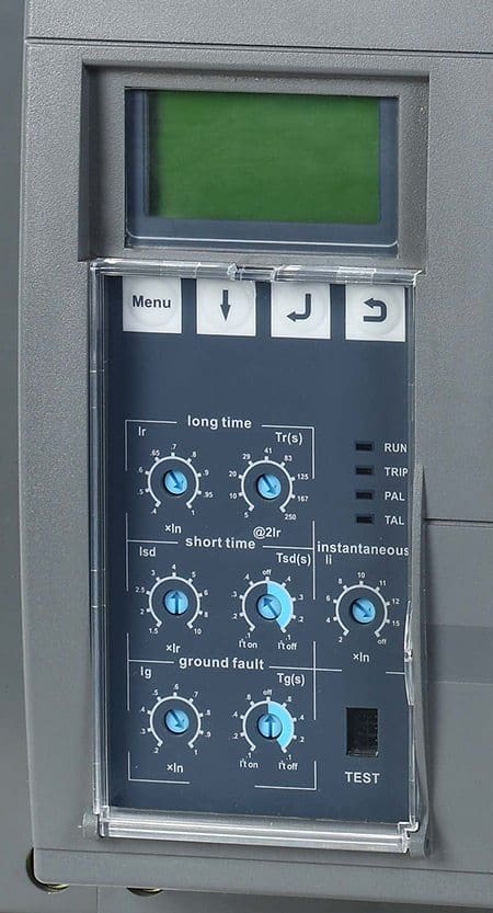
LV circuit breaker protection settings
However, with electronic trip molded case circuit breakers and insulated case circuit breakers, a built-in instantaneous override mechanism is present.
This is called the instantaneous override function, and will override the STD for medium to high level faults. The instantaneous override setting for these devices is typically 8 to 12 times the rating of the circuit breaker and will “kick in” for faults equal to or greater than the override setting.
Because of this instantaneous override, non-selective tripping can exist, similar to molded case circuit breakers and insulated case circuit breakers without short-time delay.
Thus, while short-time delay in molded case and insulated case circuit breakers can improve coordination in the overload and low level fault regions, it may not be able to assure coordination for medium and high level fault conditions.
Low Voltage Power Circuit Breakers (LVPCB) with Short-Time Delay
Short-time-delay, with settings from 6 to 30 cycles, is also available on low voltage power circuit breakers. However, with low voltage power circuit breakers an instantaneous override is not required. Thus, low voltage power circuit breakers with short-time delay can hold into faults for up to 30 cycles.
This allows the downstream device to open the fault before the upstream low voltage power circuit breaker opens.
However, if the fault is between the downstream device and the low voltage power circuit breaker, the electrical equipment can be subjected to unnecessarily high mechanical and thermal stress.
Reference // Electrical Plan Review – Overcurrent Protection and Devices, Short-Circuit Calculations, Component Protection, Selective Coordination, and Other Considerations – COOPER Bussmann (Download here)
A 440 V 60 Hz switchboard feeds a 4-wire distribution board for small loads such as socket outlets. The switchboard has a fault making capacity of 100kA rms. After applying diversity factors to the loads the total load current is 90 A. Moulded case circuit breakers (MCCBs) rated at 16 A and 32 A are to be used for the loads.
The installation will use cables having copper conductors and XLPE insulation. The cable from the switchboard to the distribution board is 20 metres in length.
A typical load cable is 15 metres in length and will carry a current of 29 A at a power factor of 0.85 lagging.
Ignore the presence of induction motors at the switchboard and find the following:
1. Choose the upstream MCCB at the switchboard and its settings
From a manufacturer’s data sheet a 125 A MCCB with an adjustable 100 A thermal release is chosen. The thermal release is set to 90 A to match the total load.
2. Choose the incoming feeder cable
From a manufacturer’s data sheet several cables can be compared for the same ambient conditions and laying arrangements. Their details are:
50 mm2 cable, maximum current 124 A, R = 0.492, X = 0.110 ohms/km.
70 mm2 cable, maximum current 159 A, R = 0.340, X = 0.106 ohms/km.
95 mm2 cable, maximum current 193 A, R = 0.247, X = 0.093 ohms/km.
The 70 mm2 cable is chosen since the rating of the 50 mm2 cable is just too low.
15. Select the largest conductor size from the above calculations
Comparing the conductor sizes found in 13. and 14. gives the larger as 10 mm2, and this size should be used. Revise the calculation of the fault current Ifd. The impedance Zc2 of the load cable is:
Add Zc2 to Zfc to give the fault impedance Zfd as:
Figure 1 – Coordination of MCCBs at a distribution board
Refrence // Switchgear and Motor Control Centres – Handbook of Electrical Engineering: For Practitioners in the Oil, Gas and Petrochemical Industry by Alan L. Sheldrake (Download here)
An MCB is a thermo-magnetic device, meaning that it has two methods of circuit interruption. A thermal mechanism, usually a bi-metallic strip, provides protection against moderate overcurrent. The heating action of the current causes the bi-metallic strip to curve and break circuit contact. This method is complemented by a solenoid designed to respond to larger currents.
A diagram of an MCB is shown in Figure 1 below.
Figure 1 – Internal view of an MCB
It should be apparent that the thermal trip has a slow response time and the solenoid trip has a rapid response time. When combined, these devices provide quite a sophisticated protection characteristic profile.
The thermal, bi-metallic characteristic is summarized in Table 1. A further co-ordination of the requirement is that of Regulation 433.1.1 (iii) which is:
I2 ≤ 1.45 × Iz where I2 is the current that causes operation of the device.
By studying Table 1 above, it can be seen that this requirement is built into the product standard for BS EN 60898 devices and is effectively the calibration of the bi-metallic strip.
The maximum rated current available for MCBs is 125A, and these BS EN 60898 devices are available with different magnetic sensitivities, denoted with a prefix B, C or D accordingly.
The different magnetic characteristics of BS EN 60898 circuit breakers are provided in Appendix 3 of BS 7671: 2008, but to illustrate the differences in the magnetic characteristics, Figure 2 shows a comparison of B, C and D types for devices of the same basic rating. A 32A circuit breaker with type C sensitivity is denoted C32, and it is a requirement of the equipment standard to apply this marking to the device.
The stated B, C or D sensitivities each have a minimum current that causes operation, and this is conventionally taken to be operation within 0.1 second. This is conventionally termed instantaneous operation or instantaneous tripping.
This minimum time convention is due to the mechanics of the circuit breaker, which will always require a certain minimum time, regardless of current for the trip mechanism to open.
Figure 2 shows that in order to achieve instantaneous tripping or tripping at 0.1 s, a 32A type B breaker requires 160A, a type C breaker 320A and a type D breaker 640A.
Table 2 //
Circuit breaker (BS EN 60898) selection for inrush current applications
Type
Manufactured magnetic trip setting (× In)
Typical applications
B
3 to 5
General domestic and resistive loads
C
5 to 10
Small motors (a few kW), small transformers fluorescent lighting and most inductive loads
D
10 to 20
DOL motors, large star delta motors, low- pressure sodium discharge lighting, larger transformers, welding machine supplies
Below these threshold currents the thermal mechanism is dominant, and has the same characteristic for all three devices. The magnetic characteristics determine the sensitivity type. Equipment connected or likely to be connected to the circuit must be assessed in terms of likely peak or inrush current.
Inrush current is the current that a load draws when the supply is switched on.
Values can range from being insignificant (a few times the normal current), 5 to 10 times normal current for iron core transformers (e.g. conventional ballast fluorescent luminaires) and up to 20 times normal current for much modern electronic equipment, including the power supplies found in user equipment.
While short-lived (often the peak current is a few milliseconds), this can cause circuit breakers to trip, but assessing the likelihood of a circuit breaker tripping is complicated. Table 2 above recommends circuit breaker types for typical inrush current applications.
Separately to inrush current, load peak current also needs to be considered. Peak current in respect of circuit breaker selection is a term used to describe a peak within the normal operation of a cyclic or time varying load.
If you have loads with significant cyclic peaks you need to confirm that the circuit breaker will not trip. This can be confirmed by studying the circuit breaker characteristic curve, but confirmation with the manufacturer may be necessary.
Voltage drop calculations using the DC-resistance formula are not always accurate for AC circuits, especially for those with a less-than-unity power factor or for those that use conductors larger than 2 AWG.
Table 1 allows engineers to perform simple ac voltage drop calculations. Table 1 was compiled using the Neher–McGrath ac-resistance calculation method, and the values presented are both reliable and conservative. This table contains completed calculations of effective impedance (Z) for the average ac circuit with an 85 percent power factor (see Calculation Example 1).
If calculations with a different power factor are necessary, Table 1 also contains the appropriate values of inductive reactance and AC resistance (see Example 2).
The basic assumptions and the limitations of Table 1 are as follows:
Capacitive reactance is ignored.
There are three conductors in a raceway.
The calculated voltage drop values are approximate.
For circuits with other parameters, the Neher–McGrath ac-resistance calculation method is used.
Calculation Example #1
A feeder has a 100 A continuous load. The system source is 240 volts, 3 phase, and the supplying circuit breaker is 125 A. The feeder is in a trade size 1¼ aluminum conduit with three 1 AWG THHN copper conductors operating at their maximum temperature rating of 75°C. The circuit length is 150 ft, and the power factor is 85 percent.
Using Table 1 below, determine the approximate voltage drop of this circuit.
Using the Table 1 column “Effective Zat 0.85 PF for Uncoated Copper Wires”, select aluminum conduit and size 1 AWG copper wire. Use the given value of 0.16 ohm per 1000 ft in the following formula:
STEP-2 // Find the line-to-line voltage drop:
STEP-3 // Find the voltage present at the load end of the circuit:
Calculation Example #2
A 270 A continuous load is present on a feeder. The circuit consists of a single 4-in. PVC conduit with three 600-kcmil XHHW/USE aluminum conductors fed from a 480 V, 3-phase, 3-wire source. The conductors are operating at their maximum rated temperature of 75°C.
If the power factor is 0.7 and the circuit length is 250 ft, is the voltage drop excessive?
See the solution //
STEP-1 // Using the Table 1 column “XL (Reactance) for All Wires”, select PVC conduit and the row for size 600 kcmil. A value of 0.039 ohm per 1000 ft is given as this XL. Next, using the column “Alternating-Current Resistance for Aluminum Wires”, select PVC conduit and the row for size 600 kcmil. A value of 0.036 ohm per 1000 ft is given as this R.
STEP-2 // Find the angle representing a power factor of 0.7.
Using a calculator with trigonometric functions or a trigonometric function table, find the arccosine (cos-1) θ of 0.7, which is 45.57 degrees. For this example, call this angle.
STEP-3 // Find the impedance (Z) corrected to 0.7 power factor (Zc):
STEP-4 // As in Calculation Example 1, find the approximate line-to-neutral voltage drop:
STEP-5 // Find the approximate line-to-line voltage drop:
STEP-6 // Find the approximate voltage drop expressed as a percentage of the circuit voltage:
STEP-7 // Find the voltage present at the load end of the circuit:
Conclusion // According to 210.19(A)(1), Informational Note No. 4, this voltage drop does not appear to be excessive.
TABLE 1 //
Alternating-Current Resistance and Reactance for 600-Volt Cables, 3-Phase, 60 Hz, 75°C (167°F)
Three Single Conductors in Conduit //
TABLE 1 – Alternating-Current Resistance and Reactance for 600-Volt Cables, 3-Phase, 60 Hz, 75°C (167°F) – Three Single Conductors in Conduit
Reference // National Electrical Code Handbook – Mark W. Earley, P.E., Jeffrey S. Sargent, Christopher D. Coache and Richard J. Roux (National Fire Protection Association, Quincy, Massachusetts)
Medium voltage networks are made up of switchboards and the connections feeding them. Let’s take a look at the eight different supply modes of these medium voltage switchboards. We’ll start with the main power supply solutions of an MV switchboard, regardless of its place in the network.
NOTE // The number of sources and the complexity of the switchboard differ according to the level of power supply security required.
Operation // One source feeds the busbar, the other provides a back-up supply. If a fault occurs on the busbar (or maintenance is carried out on it), the outgoing feeders are no longer fed.
Figure 2 – Sheme: 1 busbar with no coupler, 2 supply sources
III – 2 bus sections with coupler, 2 supply sources
Operation // Each source feeds one bus section. The bus coupler circuit-breaker can be kept closed or open. If one source is lost, the coupler circuit-breaker is closed and the other source feeds both bus sections.
If a fault occurs in a bus section (or maintenance is carried out on it), only one part of the outgoing feeders is no longer fed.
Figure 3 – Sheme: 2 bus sections with coupler, 2 supply sources
Operation // The power supply is normally provided by two parallel-connected sources. If one of these two sources is lost, the third provides a back-up supply. If a fault occurs on the busbar (or maintenance is carried out on it), the outgoing feeders are no longer fed.
Figure 4 – Sheme: 1 busbar with no coupler, 3 supply sources
V – 3 bus sections with couplers, 3 supply sources
Operation // Both bus coupler circuit-breakers can be kept open or closed. Each supply source feeds its own bus section. If one source is lost, the associated coupler circuit-breaker is closed, one source feeds two bus sections and the other feeds one bus section.
If a fault occurs on one bus section (or if maintenance is carried out on it), only one part of the outgoing feeders is no longer fed.
Figure 5 – Sheme: 3 bus sections with couplers, 3 supply sources
VI – 2 busbars, 2 connections per outgoing feeder, 2 supply sources
Operation // Each outgoing feeder can be fed by one or other of the busbars, depending on the state of the isolators which are associated with it, and only one isolator per outgoing feeder must be closed.
For example, source 1 feeds busbar BB1 and feeders Out1 and Out2. Source 2 feeds busbar BB2 and feeders Out3 and Out4. The bus coupler circuit-breaker can be kept closed or open during normal operation.
If one source is lost, the other source takes over the total power supply. If a fault occurs on a busbar (or maintenance is carried out on it), the coupler circuit-breaker is opened and the other busbar feeds all the outgoing feeders.
Operation // This arrangement is almost identical to the previous one (two busbars, two connections per feeder, two supply sources). The splitting up of the double busbars into two switchboards with coupler (via CB1 and CB2) provides greater operating flexibility.
Each busbar feeds a smaller number of feeders during normal operation.
Operation // Each source can feed one or other of the busbars via its two drawout circuit-breaker cubicles. For economic reasons, there is only one circuit-breaker for the two drawout cubicles, which are installed alongside one another. It is thus easy to move the circuit-breaker from one cubicle to the other.
Thus, if source 1 is to feed busbar BB2, the circuit-breaker is moved into the other cubicle associated with source 1.
Figure 8 – Sheme: “Duplex” distribution system
The same principle is used for the outgoing feeders. Thus, there are two drawout cubicles and only one circuit-breaker associated with each outgoing feeder. Each outgoing feeder can be fed by one or other of the busbars depending on where the circuit-breaker is positioned.
For example, source 1 feeds busbar BB1 and feeders Out1 and Out2. Source 2 feeds busbar BB2 and feeders Out3 and Out4. The bus coupler circuit-breaker can be kept closed or open during normal operation.
If one source is lost, the other source provides the total power supply. If maintenance is carried out on one of the busbars, the coupler circuit-breaker is opened and each circuit-breaker is placed on the busbar in service, so that all the outgoing feeders are fed. If a fault occurs on a busbar, it is put out of service.
Using the basic building blocks of utility power, system topology, on-site generation, and uninterruptible power supplies, the basic role of the automatic transfer system may now be defined.
In this role, the Automatic Transfer System must display the following characteristics:
Robustness – it must operate as intended, even under abnormal power system conditions, without human intervention. Just as importantly, it must be able to distinguish when a system condition does not warrant transfer to the alternate power source.
It must be able to control the switchgearas required and, additionally, must be able to pass the proper signals to the alternate power source if necessary (for example, to signal a generator when to start.
Simply stated, the role of the automatic transfer system is to provide the automatic transfer of power for its associated load group from a normal power source, such as a utility service, to an alternate power source, such as standby generation, in the event the normal source fails.
Example System Description
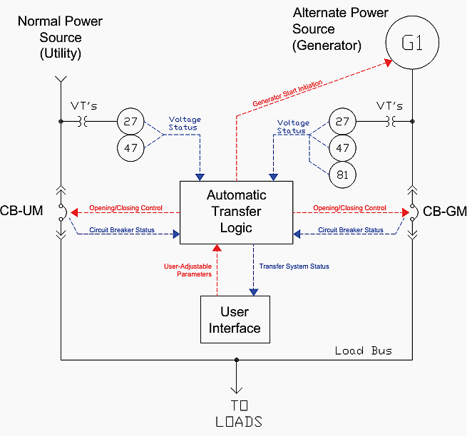
To fully illustrate the operational requirements ofa typical automatic transfer system, a more detailed representation of the system is required. For this purpose, the main-main topology arrangement used, but with the details of the automatic transfer system shown:
Figure 1 – Main-Main Automatic Transfer Scheme Detail
In Figure 1, the automatic transfer logic provides the decision-making for what automatic operations are to happen, and when. It controls the operation of the two transfer circuit breakers, CB-UM and CB-GM, and receives status inputs from those breakers. It also can initiate generator startup for the alternate power source.
Undervoltage (device 27) and negative sequence voltage (device 47) relays on each power source give the transfer logic indication of their condition. In addition, a frequency relay (device 81) is present for frequency indication of the
alternate power source.
Voltage transformers, or VT’s, step the system voltages down to instrumentation levels that can be used by these relays. A user interface allows the adjustment of certain operating parameters of the system, and updates the user onthe status of the system.
Using this example system, the operational requirements of a typical automatic transfer system will be examined.
Modes of Operation //
An essential requirement of anyautomatic transfer system is the ability to have different modes of operation. In a given mode of operation, the transfer system will respond in a given way to changing system conditions. For a different mode of operation, the transfer system will respond differently.
Two basic modes of operation, which any automatic transfer system must have, are:
Manual Mode
Automatic Mode
In the manual mode, the automatic transfer system does not perform any automatic operations, i.e., it does not respond to changing system conditions. All circuit breaker operations must be manually performed. Conversely, in the automatic mode of operation all operations, with a few emergency exceptions, are automatic, and the system will respond automatically to changing system conditions.
On the surface, this appears to be a simple arrangement, and to some extent this is true.
Good ATS design //
However, good automatic transfer system design has well-thought-out mode logic that answers the following questions:
Can the system be placed into automatic mode if system conditions are not correct (for example, if an automatically-controlled circuit breaker is in the withdrawn position or not present in the circuit breaker cell)?
What manual operations are allowed in automatic mode (for example, manual opening of circuit breakers)?
What happens if an allowed manual operation is performed on an automatically controlled device (for example, if an automatically-controlled circuit breaker is manually tripped or trips due to a fault)
Such questions are not always easy to answer. In fact, they necessitate, in a well-designed automatic transfer system, the inclusion of a third mode of operation, typically known as auto mode failure.
The three modes of operation then typically work as follows:
Selected via a selector switch position or other pre-determined user input via the user interface. Attempting to enter automatic mode if the system conditions are not correct places the system into Auto Mode Failure.
In Automatic Mode, operations for certain circuit breakers (such as main and tie circuit breakers) are automatic, however manual tripping (or breaker trip due to a fault) of automatically-controlled circuit breakers is allowed. Such manual or fault-driven operations will result in the system being placed into Auto Mode Failure.
No automatic operations occur. For automatically-controlled circuit breakers, only manual tripping (or trip due to a fault) is allowed. To leave this mode of operation, the system must be placed into manual mode.
This arrangement provides a high level of security for the transfer scheme, i.e., undesired or “nuisance” operations are minimized, enhancing safety, maintainability, and reliability of the system.
Of necessity, to make this mode logic arrangement function properly the breaker status must consist both of breaker open-closed indication and, for drawout circuit breakers, circuit breaker cell switch indication.
Circuit breaker cell switches are a feature which must not be overlooked as they are essential for the proper function of an automatic transfer scheme with drawout circuit breakers. For the same reason overcurrent trip switches for low-voltage circuit breakers or lockout relays for medium-voltage circuit breakers are also required.
Another question that frequently arises is that of a “test” mode of operation. While this could be made into a separate mode of operation, this is usually most expediently handled via voltage failure simulation test switches whilethe system is the automatic mode.
Reference // Critical-Power Automatic Transfer Systems – Design and Application by Bill Brown, P.E., Jay Guditis, Square D Critical Power Competency Center
In previous article I explained the role of the automatic transfer system and the operational requirements – three modes of operation: manual mode, automatic mode and auto mode failure.
Now let’s cover the following topics and try to explain the concept of transfering power in details //
In the automatic mode, the transfer system must be able to react to source failure by initiating transfer. For this purpose, it is necessary for the mode logic to know the condition of the normal and alternate power sources. This is typically accomplished via undervoltage (device 27) and negative-sequence voltage (device 47) relays, as shown in Figure 1.
Figure 1 – Main-Main Automatic Transfer Scheme Detail
Frequency relaying is usually not required for utility sources as the frequency isquite stable, and not affected by changing load conditions within the facility.
For standby generators, however, although they are typically controlled via isochronous governors there is a limit to the amount of power (and to sudden changes in power) that they can supply without frequency changes.
Also, at the beginning of the startup cycle of a generator the frequency is zero, and will ramp up to the nominal frequency (typically 60Hz) as part of the startup process.For these reasons, under- (and possibly over-) frequency relays (device 81) are used for generator sources in addition to the under- and negative-sequence voltage relays.
Because overvoltage can be an issue when operating on generator power (for example, if the voltage regulator fails or the generator is called upon to absorb an excessive amount of reactive power), overvoltage (device 59) relays are occasionally used as well (not shown in Figure 1).
The pickup and time delay levels for these relays are functions of the system itself and the amount of time that abnormal conditions can be tolerated. For example, the undervoltage relays are typically set to pick up when the voltage level falls to 80% of nominal. The negativesequence voltage relays are typically pre-set to respond to loss of a single phase, but may be adjustable.
Frequency relays must be set very carefully to avoid nuisance operations on normal load swings. It should be noted that these relays are typically for use by the automatic transfer system only, and are separate from the relays or generator control package functions which provide protection for the generator. Careful coordination is required to insure that the automatic transfer relays will always react before generator protective relays.
The indication from these relays to the automatic transfer logic is typically in the form of a single binary input, i.e., “source normal” or “source abnormal”. Upon receipt of a “source abnormal” signal when operating on utility power, the automatic transfer logic must respond.
Typically, this response is delayed to insure that the abnormality is not a transient condition, in order to prevent an unnecessary transfer. When the system is supplied via utility power this will allow the utility system to attempt clear the fault through reclosing.
The time delay, known as a source failure delay, may be via inverse-time characteristics built into the relays or, more typically, via a time delay built into the automatic transfer logic. This delay is typically 5-10 seconds and is a function of what type of utility reclosing is used and how long the abnormal voltage condition can be allowed to persist.
Once the source failure time delay has expired,the automatic transfer system opens the circuit breaker for the affected source, starting the automatic transfer process.
Once a transfer operation has been initiated and the system has been disconnected from its normal source of supply, a suitable time delay must be given to allow the residual voltage from spinning motors to decay before the system is transferred to the alternate source.
This time delay is known dead-bus time, and it is vital that this be taken into account in the transfer scheme design. If this is not done, there is a significant risk of both shaft and winding damage to connected motors due to the energy transfer that can occur.
For the example system of Figure 1, this will almost always be inherently be accounted for due to the generator start-up time, however the logic should incorporate controls to insure this.
In general, any time a system bus is de-energized due to automatic transfer action a dead-bus delay should be coded into the transfer logic. Typical dead-bus delays are 2 – 5s.
For the example system of Figure 1, a signal is provided to initiate generator starting. In general, this will be a requirement any time one of the sources of power is a generator or generators, unless the generator(s) is used for cogeneration aswell as standby power.
Typically, this signal is a contact closure; once the contact is closed the generator(s) will start up and will run until the contact is opened, at which time the generator will begin a cool-down cycle.
Other variations exist, however in general the management of the generator cool-down cycle should remain under control of the generator(s) control system rather than the automatic transfer system.
After the alternate source is available and the required dead-bus delay has expired, the transfer system must close the alternate-source circuit breaker to supply the system from the alternate source. In the example system of Figure 1, the alternate-source circuit breaker is CB-GM.
For a main-tie-main system as shown in Figure 2, the secondary bus tie circuit breaker would be the circuit breaker that is closed.
For the main-main topology arrangement, one of the bus tie circuit breakers would normally remain closed all of the time, and the second tie circuit breaker would be the circuit breaker that is closed to complete the transfer.
The normal source, when it returns, typically starts a timer in the automatic transfer system. This timer is present so that re-transfer will not occur until the normal source has been shown to be stable. The time delay is known as a return of source time delay and is typically set from 5 – 15 minutes.
Once the time delay has expired the return to the normal operating condition may be open-or closed-transition, and may be manually or automatically initiated.
As its name implies, open-transition re-transfer entails de-energizing the system prior to reenergizing it with the normal source. This requires a dead-bus delay as discussed above. In the example system of Figure 1, the circuit breaker CB-GM would open, a dead-bus delay would transpire, and circuit breaker CB-UM would close to complete the re-transfer.
The disadvantage to this method of re-transfer is that it requires the system to take a second outage in order to be restored to the normal source. However, it does not require additional equipment to accomplish.
Closed-transition re-transfer requires the paralleling of the normal and alternate power sources for a brief time period prior to separation from the alternate power source. Where a generator(s) is involved, this requires synchronizing the generator(s) with the normal power source.
This synchronization may be accomplished passively, by simply waiting for the generator(s) to fall into synchronism with the normal source, or actively, by driving the generator(s)into synchronism with the normal source.
In general, passive synchronization is less expensive and can be accomplished with a simple synchronism checking relay (device 25), however the generator is not guaranteed to fall into synchronism with the utility source and the resulting energy transfer during the transition can damage the generator and other system components.
Active synchronization avoids these problems, but is more expensive since an generator synchronizer and additional control signals between the automatic transfer system and generator control system are required.
The time period during which the sources are paralleled is usually very brief, no more than 2 -3 cycles, in order to keep the heightened exposure of the system which occurs to as brief a time as possible. This heightened exposure results from the elevated fault-current levels that exist with the sources in parallel, and also due to the exposure of the system to supply a fault on the normal source via the alternate source. If both the normal and alternate sources are separate utility services the utility may have restrictions on the ability to perform closed-transition re-transfer.
The advantage of closed-transition re-transfer is that the system does not have to experience another outage during re-transfer.For the example system of Figure 1, circuit breaker CB-UM would close once synchronization is achieved (passive or active), then circuit breaker CB-GM would open to complete the re-transfer.
Unusual conditions can occur during the automatic transfer process. For example, the normal power source could fail, only to be restored during the dead-bus time delay before the alternate source is connected to the system. How the automatically transfer system responds during such conditions has traditionally been a function of the skill of the transfer system designer and the requirements of the facility.
The basic philosophy for automatic transfers in mission-critical environments is to transfer the system if the condition of the normal source is in doubt, so long as the alternate power source is known to be available and it is safe to do so, and most automatic transfer systems for these environments are designed with this goal in mind.
Reference // Critical-Power Automatic Transfer Systems – Design and Application by Bill Brown, P.E., Jay Guditis, Square D Critical Power Competency Center
Selection of rated circuit breaker // The general procedure for the selection of correctly rated circuit breaker follows the following scheme of seven major questions you should answer: What is the task of the branch circuit or feeder? Which rated current / setting range? Breaking/making capacities / rated operational voltage? Any special requirements? Which type […]
Motor protection circuit breaker (MPCB) // Application-specific variations of the MCCB, these breakers combine the short-circuit and isolation functionality of the MCCB with the motor overcurrent protection of a traditional overload relay. MPCBs are UL 489 Listed as circuit breakers and verified as motor overload relays. These devices are traditionally used in two component starter applications, […]
Single line diagram (SLD) We usually depict the electrical distribution system by a graphic representation called a single line diagram (SLD). A single line can show all or part of a system. It is very versatile and comprehensive because it can depict very simple DC circuits, or a very complicated three-phase system. We use universally […]
Circuit breaker releases / Tripping units The main objective of circuit breaker tripping units and protective functions in general is to detect faults and to selectively isolate faulted parts of the system. It must also permit short clearance times to limit the fault power and the effect of arcing faults. The protective function of the […]
")


")
")
")
 of LV circuit breakers due to the switching operations")


 For Beginners")


 normal; (b) overcurrent condition")

")


")
 to open fuse switch disconnector")


")