Quantcast
Channel: circuit breaker Archives | EEP - Electrical Engineering Portal
Viewing all 150 articles
Browse latest View live

Simplify Downstream Installation with Cascading

$
0
0
Simplify Downstream Installation with Cascading

Simplify Downstream Installation with Cascading (on photo Prisma P 0,42kV switchboard with Masterpact 2500A circuit breakers and Canalis busbar systems for distribution)

Few Words About Cascading

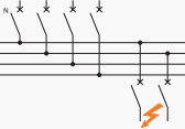
Cascading circuit breakers installation
Cascading provides circuit breakers placed downstream of a limiting circuit breaker with an enhanced breaking capacity. The limiting circuit breaker helps the circuit breaker placed downstream by limiting high short-circuit currents.

Cascading makes it possible to use a circuit-breaker with a breaking capacity lower than the short-circuit current calculated at its installation point.


Area of Cascading Application

  • Concerns all devices installed downstream of this circuit-breaker,
  • Can be extended to several consecutive devices, even if they are used in different switchboards.

The installation standards (IEC 60364) stipulate that the upstream device must have an ultimate breaking capacity Icu greater than or equal to the assumed short-circuit current at the installation point.

For downstream circuit-breakers, the ultimate breaking capacity Icu to be considered is the ultimate breaking capacity enhanced by coordination.


Implementation Techniques

Principles

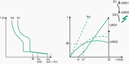
As soon as the two circuit-breakers trip (as from point IB), an arc voltage UAD1 on separation of the contacts of D1 is added to voltage UAD2 and helps, by additional limitation, circuit-breaker D2 to open.

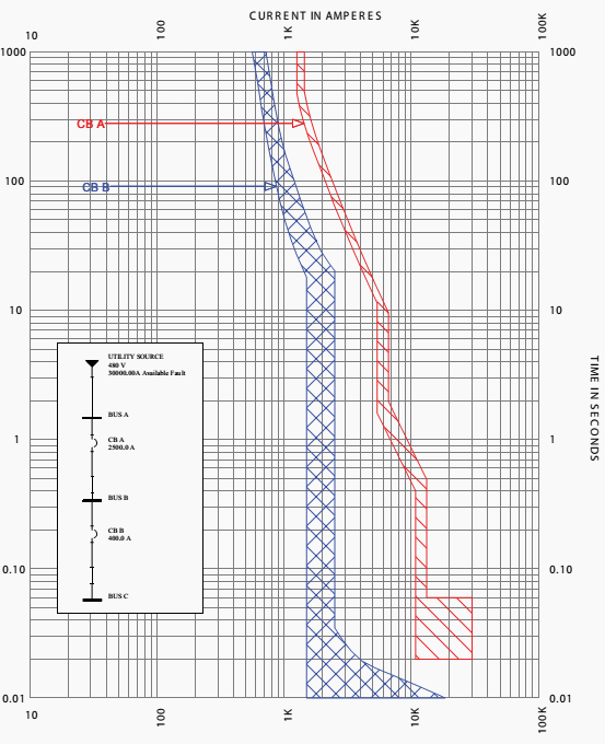
Cascading circuit breakers tripping curves

Cascading circuit breakers tripping curves


The association D1 + D2 allows an increase in performance of D2 as shown in figure 2 below:

  • Limitation curve D2,
  • Enhanced limitation curve of D2 by D1,
  • Icu D2 enhanced by D1.

In actual fact, in compliance with the recommendations of IEC 60947-2, manufacturers give directly and guarantee Icu enhanced by the association of D1 + D2.

Cascading enhanced circuit-breakers tripping curves

Cascading enhanced circuit-breakers tripping curves


In a cascade system, both the upstream and downstream devices are expected to operate simultaneously so that the fault energy is shared by the breaking devices. Unless the combination is tested for the required fault level, the performance of the combination cannot be guaranteed in the field.

After a major fault is cleared both the devices of the combination need to be thoroughly examined and replaced if necessary to ensure safe operation during any future fault in the system.

Advantages of Cascading

Cascading allows benefit to be derived from all the advantages of limitation. Thus, the effects of short-circuit currents are reduced, i.e.:

  • Electromagnetic effects,
  • Electrodynamic effects,
  • Thermal effects.

Installation of a single limiting circuit-breaker results in considerable simplifications and savings for the entire downstream installation:

  • Simplification of choice of devices by the cascading tables,
  • Savings on downstream devices. Limitation enables circuit-breakers with standard performance to be used.

Thanks to cascading, circuit breakers with breaking capacities less than the prospective short-circuit current may be installed downstream from a current limiting circuit breaker. It follows that substantial savings can be made on downstream switchgear and enclosures.

Resource: Merlin Gerin/Schneider Electric Circuit breaker application guide


Smart and Safe Protective Shutdown with Selectivity

$
0
0
Smart and safe protective shutdown with selectivity

Smart and safe protective shutdown with selectivity (on photo ABB's MNS Low Voltage Switchgear)

Safety point

From the point of view of the operational safety and reliability of an entire low-voltage installation, it is usually desirable to specifically isolate the part of a system affected by a short-circuit in order to prevent spreading of the fault.

Selectivity is intended to ensure that the protective shutdown is as close as possible to the location of the fault so that unaffected installation components can continue to operate normally.

IEC 61439 standard – The new standard for low-voltage switchgear and controlgear ASSEMBLIES – Applies to enclosures for which the rated voltage is under 1000 V AC or 1500 V DC.

This is often also desired for safety reasons and in IEC 60439-1 (low-voltage switchgear assemblies) addressed for installations that require a high level of continuity in current supply.

In buildings and industrial plants, radial distribution networks are the norm. In radial distribution systems there are several protective devices in series, usually with decreasing rated currents from the supply end to the load end.
While the operational currents decrease from the supply end to the load end, in the event of a short-circuit the same fault current will flow through all the protective devices connected in series.

By a cascading of the trip characteristics it must be ensured that only the respective protective device that is closest to the location of the fault is activated and hence the fault is selectively limited to the smallest possible part of the installation. We saw in one of the previous technical article Simplify Downstream Installation with Cascading – that cascading actually makes protection system cheaper by simplifying the downstream installation (e.g. circuit breakers).

The basic prerequisite for selectivity of protective devices connected in series is that the trip characteristic of the downstream (closer to the load) protective device is faster than that of the upstream device. And all this taking into account all tolerances and over the entire current range up to largest prospective short-circuit current.

Special attention should be paid to the area of high overcurrents, where the effects of current limitation and breaking times are significant. Thus an upstream fuse does not operate if the entire I2t of the downstream protective device (fuse, circuit breaker) is smaller than the melting I2t the fuse. An upstream circuit breaker on the other hand does not operate if the maximum cut-off current ID of the downstream protective device is smaller than the activation value of its magnetic release.

In individual cases, reference to manufacture documents and frequently the technical support of the manufacturer is required for the correct selection of devices. The basic facts are presented below.


Selectivity between fuses connected in series

Fuses connected in series act selectively if their time current-characteristic curves have sufficient mutual spacing and their tolerance bands do not touch (Figure 1).

Selectivity between fuses connected in series

Figure 1 - Selectivity between fuses connected in series


At high short-circuit currents the melting I2t value of the upstream fuse must be larger than the  breaking I2t value (melting and clearing time) of the smaller downstream fuse. This is usually the case if their rated currents differ by a factor of 1.6 or more.


Selectivity of circuit breakers connected in series

Current selectivity

In distribution networks, the rated currents of the switches decrease constantly from the transformer to the load. As the short-circuit releases normally operate at a multiple of the rated current, their release levels decrease in the same way with distance from the supply.

As the prospective short-circuit currents also become smaller with increasing distance from the supply point due to line damping, a so-called natural selectivity can be created via the current magnitude.

This means that the maximum short-circuit current with a short-circuit on the load-side of the switch 2 (Figure 2) is below the trip value of the magnetic release of switch 1.

The short-circuit currents must be known at the installation sites of the switches. Selectivity is usually not assured with short-circuit currents above the response value of the magnetic release of the upstream circuit breaker.

Current selectivity of two circuit breakers in series

Figure 2 - Current selectivity of two circuit breakers in series is given, if the prospective short-circuit current downstream of Circuit breaker 2 is smaller than the trip value of the magnetic release of Switch 1


b = Overload release
s = Short-circuit release

When assessing the current selectivity the tolerance of the short-circuit trigger (+/-20 % in accordance with IEC 60947-2) should be taken into account.


Time selectivity

If current selectivity between circuit breakers is not possible, selectivity must be achieved by cascading of the trip times, i.e. the upstream circuit breaker operates with a short delay to give the downstream circuit breaker time to clear the short-circuit.

If the short-circuit occurs between the two switches, then it will continue during the short trip delay time of the switch 1 and after lapse of this time it will be switched off by the latter (Figure 3).

Time selectivity of two circuit breakers in series

Figure 3 - Time selectivity of two circuit breakers in series


b = Overload release
s = Short-circuit release (switch 1 with short-time delay; utilization category B)

The cascading of trip times requires that Switch 1 is capable of carrying the short-circuit current during the trip delay time. This is the case when using circuit breakers of utilization category B.

The critical variable is the rated short-time current Icw that determines the magnitude of the permissible short-time current during a defined period. It is usually stated as the 1s – current and can be converted for other times with I2t = const.


Selectivity between fuse and downstream circuit breaker

Selectivity between fuse and downstream circuit breaker

Figure 4 - Selectivity between fuse and downstream circuit breaker


1 = Circuit breaker
2 = Fuse

In the overload range selectivity is given, if the trip characteristic of the overload release lies under the characteristic curve of the fuse (considering the tolerance band). In the short-circuit range selectivity is given to the extent that the total breaking time (including clearing time) of the circuit breaker is below the melting characteristic of the fuse.


Selectivity between a circuit breaker and downstream fuse

Selectivity between circuit breaker and downstream fuse

Figure 5 - Selectivity between circuit breaker and downstream fuse


1 = Circuit breaker
2 = Fuse

Selectivity in the tripping range of the short-circuit release of the circuit breaker is given when the cut-off current of the fuse is smaller than its trip value.

Selectivity and undervoltage

In a short-circuit the supply voltage breaks down at the short-circuit location. The size of the residual voltage depends on the impedance of the fault. If an electric arc is produced, the voltage is appr. 30 V to 70 V.

As the short-circuit current flows over the entire power line up to power source, along this line there is a voltage drop whose size is determined by the impedances lying between the two points.

All connected electrical consumers are affected by the voltage drop and the closer they are to the fault location the greater is this effect. Devices such as contactors or undervoltage releases of circuit breakers may trip depending on the amount and duration of the voltage drop.

In order to guarantee operational continuity, suitable off-delays or remaking equipment should be provided. When short-circuits are broken by current limiting circuit breakers, voltage break-downs are so short that no disruptions should be expected.

Resource: Allen Bradley – Low Voltage Switchgear and Controlgear

Application of Circuit Breakers in IT Networks

$
0
0
Application of Circuit Breakers in IT Networks

Application of Circuit Breakers in IT Networks (on photo LV switchboard by MaTech Magyar Technologiai Kft.)

Introduction

IT supplies are used to prevent that a ground fault leads to immediate disconnection of the affected circuit like in a grounded system. Although a first ground fault results in a displacement of the potential of the entire supply, continued operation is still temporarily possible.

Special ground fault monitoring equipment reports any ground faults and hence makes it possible to quickly rectify the fault – often without disruption to the operation of the plant.

The situation is similar in supplies with high impedance grounding.

If however a second ground fault occurs in another phase, there is a short-circuit that must be immediately cleared by the short-circuit protective device. The voltage to be switched off varies depending on the locations of the short-circuits (Figure 1).

This results in different voltage levels to be switched off by the short-circuit protective device and in the case of circuit breakers to different required breaking capacities.
Double ground faults on the load side of the circuit breakers do not cause increased stress.

Figure 1 - Double ground faults on the load side of the circuit breakers do not cause increased stress.


If, however, there is one ground fault on the supply side and the other on the load-side, a significantly higher breaking capacity is required because of the increased voltage load.

If both short-circuits occur on the load-side of the circuit breaker, the breaking work is shared between two contacts and the required breaking capacity corresponds to the normal 3-phase values.

If the location of one short-circuit is on the supply-side of the circuit breaker and the second short-circuit on the load-side, then one contact only of the circuit breaker has to perform the total breaking work and this at phase-to-phase voltage. In this case, the significantly lower single pole breaking capacity of the circuit breaker at the phase-to-phase voltage is critical. If the values cannot be obtained from the device documents, an inquiry should be made. If the short-circuit current at the installation site exceeds the single pole switching capacity of the circuit breaker, then a back-up fuse is required.

For three-pole short-circuits there is no difference between IT supplies and other supply types.

The ultimate short-circuit breaking capacity Icuand the service short-circuit breaking capacity Ics continue to apply. Circuit breakers under IEC 60947-2 are suitable for use in IT supplies, if they are not marked with the symbol Symbol not for IT. Testing is in accordance with Annex H.

Resource: Allen Bradley – Low Voltage Switchgear and Controlgear

Methods of Controlling Lightning Overvoltages in HV

$
0
0
Methods of Controlling Lightning Overvoltages in HV

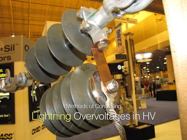
Hubbell's improved protecta-lite transmission line arrester line has been simplified with fewer parts and less risk of parts wearing out. Several steel plated components were replaced with one copper strap. The strap makes installation easier and reduces the wear points. Vibration and wear are more important on transmission line arresters due to the fact that they are more exposed to wind and vibration.

Introduction

For well shielded transmission lines, the backflashover condition, close to the substation, is of prime concern for determining the location and number of surge arresters required to achieve insulation coordination of the substation for lightning surges.

The risk of a backflashover can be reduced by keeping the tower foot impedances to a minimum, particularly close to the substation (first five to seven towers).

The terminal tower is usually bonded to the substation earth mat and will have a very low grounding impedance (1 ohm).

However, the procedure for ‘gapping’ down on the first three or four towers where line co-ordinating gaps are reduced in an attempt to reduce incoming voltage surges will increase the risk of a ‘close-in’ backflashover.


Location of Surge Arresters

Considering the system shown in Figure 1, where the transmission line is directly connected to a 420 kV GIS (Gas Insulated Switchgear), a computer model can be created to take into account the parameters previously discussed.

A transient study would reveal the level of lightning stroke current required to cause a backflashover.

System schematic diagram

Figure 1 - System schematic diagram


Then according to the number of line flashes 100 km/yr calculated for the transmission line and by using the probability curve for lightning current amplitude, a return time for this stroke current can be assessed (Le. 1 in 400 yrs, 1 in 10 yrs, etc.) in, say, the first kilometre of the line.

The voltage then arriving at the substation can be evaluated and compared with the LIWL (Lightning impulse withstand level) for the substation equipment.

The open-circuit-breaker condition must be studied here, since if the line circuit-breaker is open the surge voltage will ‘double-up’ at the open terminal. Various levels of stroke current can be simulated at different tower locations and the resultant substation overvoltages can be assessed.

If it is considered that the LIWL of the substation will be exceeded or that there is insufficient margin between the calculated surge levels and the LIWL to produce an acceptable risk, then surge arrester protection must be applied.

The rating of the MOA (metal oxide surgearresters) will have been assessed from TOV (Temporary overvoltage) requirements, and from the manufacturer’s data a surge arrester model can be included in the system model. Repeating the various studies will reveal the protective level of the arrester and from this the safety factor for this system configuration can be assessed.

IEC 60071 recommends a safety factor of 1.25 for 420 kV equipment (safety factor = LIWL / protective level).

The surge arrester current calculated for this condition should be the ‘worst’ case and can therefore be used to assess the nominal discharge current requirement of the surge arrester (5 kA, 10 kA or 20 kA).

(IEC 60091-1 is the international standard for surge arresters [16], and an accompanying guide isavailable which contains detailed information on the application of surge arresters).

To make full use of the MOA protective level the arrester should be placed as close as possible to the equipment being protected.

In the case of the open line circuit-breaker this may well be 10-20 m distance.

Dependent on the rate of rise of the surge voltage, a voltage greater than the residual voltage at the surge arrester location will be experienced at the terminals of the open-circuit-breaker. This must be taken into account when assessing the substation overvoltage.

Figure 2 illustrates the surge voltage profile of the GIS (Gas Insulated Switchgear) with the line circuit-breaker closed. It shows that additional surge arresters may be required because of the distances involved in the layout of the substation.

Analysis of lightning surge for gas insulated substation

Figure 2 - Analysis of lightning surge for gas insulated substation


It then follows that surge arresters have a ‘protective length’  which is sensitive to the rate of rise of the incoming surge voltage, and this must be taken into consideration when assessing the lighting overvoltage on equipment remote from the surge arrester.

Resource: High voltage engineering and testing - Hugh M. Ryan

Using Protective Relay For Fighting Against Faults

$
0
0
Using Protective Relay For Fighting Against Faults

Using Protective Relay For Fighting Against Faults

Content

  1. Introduction to Protective Relay
  2. Working Principle of Protective Scheme
  3. What is Relay?
  4. Functions of Protective Relay
  5. Desirable qualities of protective relaying
  6. Terminology of protective relay
  7. History of Protective Relay
  8. Types of Relays
  9. Types of Relay based on Relay Operation Mechanism
  10. Protective relay testing: Test relays of all generations (VIDEO)

Introduction to Protective Relay

Protective relay works in the way of sensing and control devices to accomplish its function. Under normal power system operation, a protective relay remains idle and serves no active function.

But when fault or undesirable condition arrives Protective Relay must be operated and function correctly.

A Power System consists of various electrical components like Generator, transformers, transmission lines, isolators, circuit breakers, bus bars, cables, relays, instrument transformers, distribution feeders, and various types of loads.

Faults may occur in any part of power system as a short circuit and earth fault. Fault may be Single Line to Ground, Double Line to Ground, Line to Line, three phase short circuit etc. This results in flow of heavy fault current through the system.

Fault level also depends on the fault impedance which depends on the location of fault referred from the source side. To calculate fault level at various points in the power system, fault analysis is necessary.

The protection system operates and isolates the faulty section. The operation of the protection system should be fast and selective i.e. it should isolate only the faulty section in the shortest possible time causing minimum disturbance to the system. Also, if main protection fails to operate, there should be a backup protection for which proper relay co-ordination is necessary.

Failure of a protective relay can result in devastating equipment damage and prolonged downtime.

Go to Content ↑


Working Principle of Protective Scheme

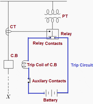
Protective relaying senses the abnormal condition in a part of power system and gives an alarm or isolates that part from healthy system. Protective relaying is a team work of CT, PT, protective relays, time delay relays, trip circuits, circuit breakers etc.

Protective relaying plays an important role in minimizing the faults and also in minimizing the damage in the event of faults.

Basic connections of circuit breaker control for the opening operation

Basic connections of circuit breaker control for the opening operation


Figure above shows basic connections of circuit breaker control for the opening operation. The protected circuit X is shown by dashed line. When a fault occurs in the protected circuit the relay connected to CT and PT actuates and closes its contacts.

Current flows from battery in the trip circuit. As the trip coil of circuit breaker is energized, the circuit breaker operating mechanism is actuated and it operates for the opening operation.

Thus the fault is sensed and the trip circuit is actuated by the relay and the faulty part is isolated.

Go to Content ↑


What is Relay?

A relay is automatic device which senses an abnormal condition of electrical circuit and closes its contacts.

These contacts in turns close and complete the circuit breaker trip coil circuit hence make the circuit breaker tripped for disconnecting the faulty portion of the electrical circuit from rest of the healthy circuit.

Go to Content ↑


Functions of Protective Relay

These are the main functions of protective relay:

  1. To sound an alarm or to close the trip circuit of a circuit breaker so as to disconnect Faulty Section.
  2. To disconnect the abnormally operating part so as to prevent subsequent faults. For e.g. Overload protection of a machine not only protects the machine but also prevents Insulation failure.
  3. To isolate or disconnect faulted circuits or equipment quickly from the remainder of the system so the system can continue to function and to minimize the damage to the faulty part. For example – If machine is disconnected immediately after a winding fault, only a few coils may need replacement. But if the fault is sustained, the entire winding may get damaged and machine may be beyond repairs.
  4. To localize the effect of fault by disconnecting the faulty part from healthy part, causing   least disturbance to the healthy system.
  5. To disconnect the faulty part quickly so as to improve system stability, service continuity and system performance. Transient stability can be improved by means of improved   protective relaying.
  6. To minimize hazards to personnel.

Go to Content ↑

Desirable Qualities of Protective Relaying

  1. Selectivity,
  2. Discrimination
  3. Stability
  4. Sensitivity,
  5. Power consumption
  6. System Security
  7. Reliability
  8. Adequateness
  9. Speed & Time

Go to Content ↑


Terminology of protective relay

Pickup level of actuating signal: The value of actuating quantity (voltage or current) which is on threshold above which the relay initiates to be operated. If the value of actuating quantity is increased, the electromagnetic effect of the relay coil is increased and above a certain level of actuating quantity the moving mechanism of the relay just starts to move.

Reset level: The value of current or voltage below which a relay opens its contacts and comes in original position.

Operating Time of Relay: Just after exceeding pickup level of actuating quantity the moving mechanism (for example rotating disc) of relay starts moving and it ultimately close the relay contacts at the end of its journey. The time which elapses between the instant when actuating quantity exceeds the pickup value to the instant when the relay contacts close.

Reset time of Relay: The time which elapses between the instant when the actuating quantity becomes less than the reset value to the instant when the relay contacts returns to its normal position.

Reach of Relay: A distance relay operates whenever the distance seen by the relay is less than the pre-specified impedance. The actuating impedance in the relay is the function of distance in a distance protection relay. This impedance or corresponding distance is called reach of the relay.

Go to Content ↑


History of Protective Relay

The evolution of protective relays begins with the electromechanical relays. Over the past decade it upgraded from electromechanical to solid state technologies to predominate use of microprocessors and microcontrollers.

The timeline of the development of protective relays is shown below:

1900 to 19631963 to 19721972 to 19801980 to 1990
Electromechanical RelayStatic RelayDigital RelayNumerical Relay
1925=Single Disc Type Relay (Single Input)1963=Static Relay  (All Purpose)1980=Digital Type Relay (All Purpose)1990=Numerical Type Relay (All Purpose)
1961=Single Cup Type Relay (Impedance Relay)1972=Static Relay with self checking           (All Purpose)

Go to Content ↑


Types of Relays

Types of protection relays are mainly:

A. Based on Characteristic:

  1. Definite time Relays.
  2. Inverse definite minimum time Relays (IDMT)
  3. Instantaneous Relays
  4. IDMT with Instantaneous.
  5. Stepped Characteristic
  6. Programmed Switches
  7. Voltage restraint over current relay

B. Based on logic:

  1. Differential
  2. Unbalance
  3. Neutral Displacement
  4. Directional
  5. Restricted Earth Fault
  6. Over Fluxing
  7. Distance Schemes
  8. Bus bar Protection
  9. Reverse Power Relays
  10. Loss of excitation
  11. Negative Phase Sequence Relays etc.

C. Based on Actuating parameter:

  1. Current Relays
  2. Voltage Relays
  3. Frequency Relays
  4. Power Relays etc.

D. Based on Operation Mechanism:

1. Electro Magnetic Relay
2. Static Relay
……• Analog Relay
……• Digital Relay
……• Numerical /Microprocessor Relay
3. Mechanical relay

  • Thermal
    • OT Trip (Oil Temperature Trip)
    • WT Trip (Winding Temperature Trip)
    • Bearing Temp Trip etc.
  • Float Type
    • Buchholz
    • OSR
    • PRV
    • Water level Controls etc.
  • Pressure Switches
  • Mechanical Interlocks
  • Pole discrepancy Relay

E. Based on Applications

  1. Primary Relays
  2. Backup Relays

Go to Content ↑


Types of Relay based on Relay Operation Mechanism

1. Electromagnetic Relay

Electromagnetic relays are further categorized under two following categories.

1.1 Electromagnetic Attraction Relay
This Relay works on Electromagnetic Attraction Principle

1.2 Electromagnetic Induction Relay
This Relay works on Electromagnetic Induction Principle


2. Solid State (Static) Relay

Solid-state (and static) relays are further categorized under following designations:

2.1 Analog Relay
In Analog relays are measured quantities are converted into lower voltage but similar signals, which are then combined or compared directly to reference values in level detectors to produce the desired output.

2.2 Digital Relay
In Digital relays measured ac quantities are manipulated in analogue form and subsequently converted into square-wave (binary) voltages. Logic circuits or microprocessors compare the phase relationships of the square waves to make a trip decision.

2.3 Numerical Relay
In Numerical relays measured ac quantities are sequentially sampled and converted into numeric data form. A microprocessor performs mathematical and/or logical operations on the data to make trip decisions.

Go to Content ↑


Protective relay testing: Test relays of all generations (VIDEO)

Cant see this video? Click here to watch it on Youtube.

Go to Content ↑


References

  • Handbook of Switchgear –Bhel
  • Digital/Numerical Relays -T.S.M. Rao

Short-Circuit Switching Capacity Definition

$
0
0
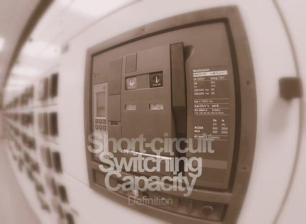
Short-circuit Switching Capacity Definition

Short-circuit Switching Capacity Definition (photo by M. Diskovic)

What is the switching capacity?

The switching capacity is the r.m.s value of a current at a given power factor cosφ as well as a given rated voltage at which a switchgear or a fuse can still shut-off under specified conditions in an operationally safe way.

Both the short-circuit making capacity as well as the short-circuit breaking capacity of circuit breakers must be larger than or equal to the prospective short-circuit current at the place of installation.

If this is not the case, then a suitable backup protection (for example a fuse) should be provided to ensure the required switching capacity of the device combination.

Data regarding devices for backup protection are given in the technical documentation.


Rated short-circuit making capacity Icm

The rated short-circuit making capacity Icm is a quantity that according to regulations must be in a certain ratio to the rated ultimate short-circuit breaking capacity Icu and that has to be guaranteed by the device manufacturer.

This is not a variable that must be considered by the user, however it ensures that a circuit breaker is in the position to connect onto a short-circuit and to disconnect it subsequently.

Rated short-circuit breaking capacity Icu and Ics

IEC 60947-2 makes distinction between the rated ultimate short-circuit breaking capacity Icu and the rated service short-circuit breaking capacity Ics :


- Rated ultimate short-circuit breaking capacity Icu

Icu is the maximum breaking capacity of a circuit breaker at an associated rated operational voltage and under specified conditions. Icu is expressed in kA and must be at least as large as the prospective short-circuit current at the site of installation.

Circuit breakers that have switched-off at the level of the ultimate short-circuit breaking capacity, are reduced serviceable afterwards and should at least be checked regarding functionality. There may be changes in the overload trip characteristic and increased temperature rise due to the erosion of contact material.


- Rated service short-circuit interrupting capacity Ics

Ics values are usually lower than the values for Icu. Circuit breakers that have been switching-off at the level of the service short-circuit breaking capacity continue to be serviceable afterward.

In plants in which interruptions to operations must be kept as short as possible, product selection should be carried-out based on Ics.


- Breaking capacity of fuses

The same applies to fuses as to circuit breakers with respect to the Icu: at the given rated operational voltage, the rated breaking capacity must be at least as large as the prospective short-circuit current at the site of installation.

Resource: Low-Voltage Switchgear and Controlgear – Allen-Bradley

Generalities and Discrimination Between RCDs

$
0
0
Generalities and Discrimination Between RCDs

Generalities and Discrimination Between Residual Current Devices (RCDs)

Generalities on Residual Current Circuit-Breakers

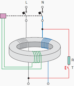
The operating principle of the residual current release is basically the detection of an earth fault current, by means of a toroid transformer which embraces all the live conductors, included the neutral if distributed.

In absence of an earth fault, the vectorial sum of the currents IΔ is equal to zero.

In case of an earth fault, if the IΔ value exceeds the rated residual operating current IΔn, the circuit at the secondary side of the toroid sends a command signal to a dedicated opening coil causing the tripping of the circuit-breaker.

Operating principle of the residual current device

Figure 1 - Operating principle of the residual current device

Classifications of RCDs

A first classification of RCDs can be made according to the type of the fault current they can detect:

  1. AC type: the tripping is ensured for residual sinusoidal alternating currents, whether suddenly applied or slowly rising;
  2. A type: tripping is ensured for residual sinusoidal alternating currents and residual pulsating direct currents, whether suddenly applied or slowly rising;
  3. B type: tripping is ensured for residual direct currents, for residual sinusoidal alternating currents and residual pulsating direct currents, whether suddenly applied or slowly rising.

Another classification referred to the operating time delay is:

  1. Undelayed type;
  2. Time delayed S-type.

RCDs can be coupled, or not, with other devices; it is possible to distinguish among:

  1. Pure residual current circuit-breakers (RCCBs)
    They have only the residual current release and can protect only against earth fault. They must be coupled with thermomagnetic circuit-breakers or fuses, for the protection against thermal and dynamical stresses;
  2. Residual current circuit-breakers with overcurrent protection (RCBOs)
    They are the combination of a thermomagnetic circuit-breaker and a RCD; for this reason, they provide the protection against both overcurrents as well as earth fault current;
  3. Residual current circuit-breakers with external toroid
    They are used in industrial plants with high currents.

They are composed by a release connected to an external toroid with a winding for the detection of the residual current; in case of earth fault, a signal commands the opening mechanism of a circuit-breaker or a line contactor.

RCD Operation

Given IΔn the operating residual current, a very important parameter for residual current devices is the residual non-operating current, which represents the maximum value of the residual current which does not cause the circuit-breaker trip; it is equal to 0.5 IΔn.

Therefore, it is possible to conclude that:

  • for IΔ < 0.5⋅IΔn the RCD shall not operate;
  • for 0.5⋅IΔn < IΔ < IΔn the RCD could operate;
  • for IΔ > IΔn the RCD shall operate.

For the choice of the rated operating residual current, it is necessary to consider, in addition to the coordination with the earthing system, also the whole of the leakage currents in the plant.

Their vectorial sums on each phase shall not be greater than 0.5⋅IΔn. in order to avoid unwanted tripping.


Discrimination between RCDs

The Standard IEC 60364-5-53 states that discrimination between residual current protective devices installed in series may be required for service reasons, particularly when safety is involved, to provide continuity of supply to the parts of the installation not involved by the fault, if any.

This discrimination can be achieved by selecting and installing RCDs in order to provide the disconnection from the supply by the RCD closest to the fault.

There are two types of discrimination between RCDs:

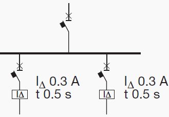
Horizontal discrimination

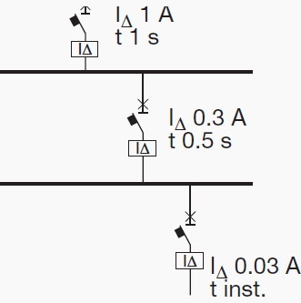
Horizontal discrimination between RCDs

Figure 2 - Horizontal discrimination between RCDs


It provides the protection of each line by using a dedicated residual current circuit-breaker; in this way, in case of earth fault, only the faulted line is disconnected, since the other RCDs do not detect any fault current.

However, it is necessary to provide protective measures against indirect contacts in the part of the switchboard and of the plant upstream the RCD;


Vertical discrimination

Vertical discrimination between RCDs

Figure 3 - Vertical discrimination between RCDs


It is realized by using RCDs connected in series.

Conditions

According to IEC 60364-5-53, to ensure discrimination between two residual current protective devices in series, these devices shall satisfy both the following conditions:

  1. The non-actuating time-current characteristic of the residual current protective device located on the supply side (upstream) shall lie above the total operating time-current characteristic of the residual current protective device located on the load side (downstream);
  2. The rated residual operating current on the device located on the supply side shall be higher than that of the residual current protective device located on the load side.

The Non-Actuating Time-Current Characteristic

The non-actuating time-current characteristic is the curve reporting the maximum time value during which a residual current greater than the residual non-operating current (equal to 0.5.IΔn) involves the residual current circuit breaker without causing the tripping.

As a conclusion, discrimination between two RCDs connected in series can be achieved:
  1. For S type residual current circuit-breakers, located on the supply side, (complying with IEC 61008-1 and IEC 61009), time-delayed type, by choosing general type circuit-breakers located downstream with IΔn equal to one third of IΔn of the upstream ones;
  2. For electronic residual current releases by choosing the upstream device with time and current thresholds directly greater than the downstream device, keeping carefully into consideration the tolerances.

For the protection against indirect contacts in distribution circuits in TT system, the maximum disconnecting time at IΔn shall not exceed 1 s (IEC 60364-4-41, §413.1)

Resource: Electrical Installation Handbook (part II) – ABB

High Voltage Substations Overview (part 1)

$
0
0
Substations and Distribution Substations Overview

Substations and Distribution Substations Overview (Photo by Ipco Group)

Introduction

High voltage substations are interconnection points within the power transmission and distribution systems between regions and countries.

Different applications of substations lead to high voltage substations with and without power transformers:

  1. Step up from a generator voltage level to a high voltage system (MV/HV)
    - Power plants (in load centers)
    - Renewable power plants (e.g., windfarms)
  2. Transform voltage levels within the high voltage system (HV/HV)
  3. Step down to medium voltage level of a distribution system (HV/MV)
  4. Interconnection in the same voltage level

Scope

High voltage substations comprise not only the high voltage equipment which is relevant for the functionality in the power supply system.

High voltage substations are planned and constructed comprising high voltage switchgear, medium voltage switchgear, major components such as high voltage equipment and transformers, as well as all ancillary equipment such as auxiliaries, control systems, protective equipment and so on, on a turnkey basis or even as general contractor.

The installations supplied worldwide range from basic substations with a single busbar to interconnection substations with multiple busbars, or a breaker–and–half arrangement for rated voltages up to 800 kV, rated currents up to 8,000A.

A and short circuit currents up to 100 kA.


Circuit configuration

High Voltage Substation

High Voltage Substation

High voltage substations are points in the power system where power can be pooled from generating sources, distributed and transformed, and delivered to the load points.

Substations are interconnected with each other, so that the power system becomes a meshed network.
This increases the reliability of the power supply system by providing alternate paths for flow of power to take care of any contingency, so that power delivery to the loads is maintained and the generators do not face any outage.

The high voltage substation is critical component in the power system, and the reliability of the power system depends upon the substation. Therefore, the circuit configuration of the high voltage substation has to be selected carefully.

Busbars are the part of the substation where all the power is concentrated from the incoming feeders, and distributed to the outgoing feeders. That means that the reliability of any high voltage substation depends on the reliability of the busbars present in the power system.

An outage of any busbar can have dramatic effects on the power system.

An outage of a busbar leads to the outage of the transmission lines connected to it.

As a result, the power flow shifts to the surviving healthy lines that are now carrying more power than they are capable of. This leads to tripping of these lines, and the cascading effect goes on until there is a blackout or similar situation.

The importance of busbar reliability should be kept in mind when taking a look at the different busbar systems that are prevalent.


Protective measures

The protective measures can be categorized as personal protection and functional protection of the substations.

Personal protection

  1. Protective measures against direct contact, i.e., through appropriate covering, obstruction, through sufficient clearance appropriate positioned protective devices, and minimum height
  2. Protective measures against indirect touching by means of relevant earthing measures in accordance with IEC 61936/DIN VDE 0101 or other required standards
  3. Protective measures during work on equipment, i.e., installation must be planned so that the specifications of DIN EN 50110 (VDE 0105) (e.g., five safety rules) are observed.

Functional protection

  1. Protective measures during operation, e.g., use of switchgear interlocking equipment
  2. Protective measures against voltage surges and lightning strikes
  3. Protective measures against fire, water and, if applicable, noise

Stresses

  1. Electrical stresses, e.g., rated current, short circuit current, adequate creepage distances and clearances
  2. Mechanical stresses (normal stressing), e.g., weight, static and dynamic loads, ice, wind
  3. Mechanical stresses (exceptional stresses), e.g., weight and constant loads in simultaneous combination with maximum switching forces or short circuit forces, etc.
  4. Special stresses, e.g., caused by installation altitudes of more than 1,000 m above sea level, or by earthquakes

Arrangement and modules

High Voltage Substation Elements

High Voltage Substation Elements (photo from Idec Group)


Arrangement

The system is off the enclosed 1-phase or 3-phase type.

The assembly consists of completely separate pressurized sections, and is thus designed to minimize any danger to the operating staff and risk of damage to adjacent sections, even if there should be trouble with the equipment.

Rupture diaphragms are provided to prevent the enclosures from bursting discs in an uncontrolled manner. Suitable deflectors provide protection for the operating personnel.

For maximum operating reliability, internal relief devises are not installed, because these would affect adjacent compartments.

The modular design, complete segregation, arc-proof bushing and plug-in connections allow speedy removal and replacement of any section with only minimal effects on the remaining pressurized switchgear.


Busbars

All busbars of the enclosed 3-phase or the 1-phase type are connected with plug from the one bay to the next.


Circuit breakers

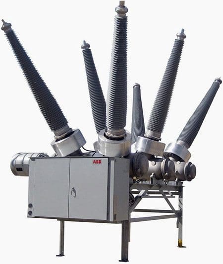
ABB - High voltage dead-tank circuit breaker 362 kV, max. 63 kA 362PMI

ABB - High voltage dead-tank circuit breaker 362 kV, max. 63 kA 362PMI


The circuit breakers operate according to the dynamic self-compression principle. The number of interrupting units per phase depends on the circuit breaker’s performance. The arcing chambers and the circuit breaker contacts are freely accessibly.

The circuit breaker is suitable for out-of-phase switching and designed to minimize overvoltages. The specified arc interruption performance has to be consistent across the entire operating range, from line-charging currents to full short circuit currents.

The circuit breaker is designed to withstand at least 10 operations (depending on the voltage levels) at full short circuit rating.

Opening the circuit breaker for service or maintenance is not necessary. The maximum tolerance for phase displacement is 3ms, that is, the time between the first and the last pole’s opening or closing.

standard station battery that is required for control and tripping may also be used for recharging the operating mechanism.

The drive and the energy storage system are provided by a stored energy spring mechanism that holds sufficient energy for all standard IEC close-open duty cycles.

The control system provides alarms signals and internal interlocks but inhibits tripping or closing of the circuit breaker when the energy capacity in the energy storage system is insufficient or the SF6 density within the circuit breaker drops below the minimum permissible level.


Disconnectors

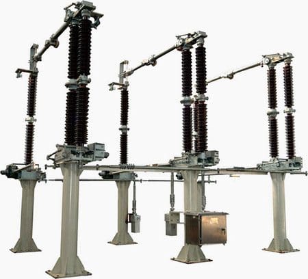
Transmission line disconnect switch

Transmission line disconnect switch (photo by Efrem Oshinsky @ Flickr)


All disconectors (isolators) are of the single-break type.

DC motor operation (110, 125, 220 or 250 V) which is fully suited to remote operation, and a manual emergency operating mechanism are provided. Each motor operating mechanism is self-contained and equipped with auxiliary switches in addition to the mechanical indicators.

The bearings are lubricated for life.


Earthing switches

High voltage outdoor earthing switch

High voltage outdoor earthing switch (126kV, 252kV) - Chint Electric Co.,Ltd.


Work-in progress earthing switches are generally provided on either side of the circuit breaker. Additional earthing switches may be used to earth busbar sections or other groups of the assembly.

DC motor operation (110, 125, 220 or 250 V) that is fully suited for remote operation and a manual emergency operating mechanism are provided. Each motor operating mechanism is self-contained and equipped with auxiliary position switches in addition to the mechanical indicators. The bearings are lubricated for life. Make proof high-speed earthing switches are generally installed at the cable and overhead line terminals.

They are equipped with a rapid closing mechanism to provide short circuit making capacity.


Instrument transformers

SF6 gas insulated high-voltage current transformer (72.5 - 800 KV) - Trench Group

SF6 gas insulated high-voltage current transformer (72.5 - 800 KV) - Trench Group


Current transformers (CTs) are of the dry type design. Epoxy resin is not used for insulation purposes. Voltage transformers are of the inductive type, with ratings up to 200 VA.


Cable terminations

1-phase or 3-phase, SF6 gas insulated, metal enclosed cable end housing are provided. The cable manufacturer has to supply the stress cone and suitable sealings to prevent oil or gas from leaking into the SF6 switchgear.

The cable end housing is suitable for oil type, gas-pressure type cables with plastic insulation (PE, PVC, etc.).

Additionally, devices for safety isolating a feeder cable and connecting a high voltage test cable to the switchgear or cable will be provided.


Overhead line terminations

The terminations for connecting overhead lines come complete with SF6-to-air bushings but without line clamps.


Control and monitoring

As a standard, an electromechanical or solid-state interlocking control board is supplied for each switchgear bay. This fault-tolerant interlocking system prevents all operating malfunctions.

Mimic diagrams and position indicators provide the operating personnel with clear operating instructions. Provisions for remote control are included. Gas compartments are constantly monitored by density monitors that provide alarm and blocking signals via contacts.

To be continued…

References:

- SIEMENS Substations Guide
- Andreas Goutis, ‘Electrical drawing, Part 1’


Things You Should Know About Medium Voltage GIS

$
0
0
Things You Should Know About Medium Voltage GIS

Things You Should Know About Medium Voltage GIS

Content

  1. Environmental Concerns
  2. Safety Concerns
  3. Special Handling Procedures
  4. Installation Concerns
  5. Operation and Maintenance Concerns
  6. End of Life / Recycling Concerns
  7. Conclusion

Introduction to GIS (Gas Insulated Switchgear)

Medium voltage (5-38 kV) gas insulated switchgear (GIS) differs greatly from the medium voltage AIS – Air insulated switchgear commonly used in North America Instead of using air and solid insulation materials, GIS switchgear has the vacuum interrupter and bare bus conductors in a sealed housing filled with an insulating gas.


1. Environmental Concerns

The insulating gas used in MV GIS switchgear, sulfur hexafluoride (SF6), is a highly potent greenhouse gas with a global warming potential 23,900 times greater than CO2. SF6 also has an atmospheric life of 3,200 years, so it will contribute to global warming for a very long time.

One pound of SF6 has the global warming equivalent of 11 tons of CO2.

(Source: EPA website www.epa.gov/electricpower-sf6)

Go to Content ↑


2. Safety Concerns

In its normal state, SF6 gas is:

  1. Colorless,
  2. Odorless,
  3. Non-flammable, and
  4. Non-toxic to humans.

However, under high temperature conditions (> 350 degrees F), SF6 decomposes into products that are toxic and corrosive. Decomposition by-products can occur when SF6 is exposed to spark discharges, partial discharges, switching arcs and failure arcing.

These byproducts, in the form of gases or powders, can cause the following conditions in humans:

  1. irritation to the eyes, nose, and throat,
  2. pulmonary edema and
  3. other lung damage, skin and eye burns, nasal congestion, bronchitis;
  4. powders may cause rashes.

(Source: EPA website www.epa.gov/electricpower-sf6)

ANSI certification results in equipment that meets rigorous U.S. operating requirements. GIS equipment is not tested to these standards, and definitely is not tested to IEEE guide for testing metal-enclosed switchgear for internal arcing faults. IEC 62271-200 – Metal enclosed MV switchgear, accepts internal arc tests to be performed with air instead of SF6, for environmental reasons.

However, it should be noted that the test results may differ if the tests were done with SF6.

When a dielectric failure occurs in a GIS, the arc generally will not be extinguished by the SF6, and could lead to internal pressure build up and cause holes in metal walls due to concentrated buming of the arc. GIS manufacturers just state that the GIS equipment is “inherently” arc resistant, but in reality an arc can very well live within the GIS.

Also it is well known that all SF6 containments leak, therefore, the chances of having an issue with GIS is more prevalent than ever having an arc issue within non arc resistant switchgear.

Utilizing other solutions, such as designs that use complete single pole solid insulation, partial discharge sensors for insulation diagnostics, and remote racking for safety, the non arc resistant solution easily exceeds the safety of GIS.

Go to Content ↑


3. Special Handling Procedures

Due to the safety concems, special handling procedures are recommended for heavily arced SF6 including the use of personal protective equipment (PPE – i.e., respiratory device, protective clothing such as rubber gloves, footwear, goggles) for removal/handling of solid SF6 byproducts.

Contaminated SF6 gas must either be filtered on-site using special mobile equipment or removed for off-site filtering or destruction using trained personnel.

(Source: EPA website www.epagovlelectricpower-sf6)

Go to Content ↑


4. Installation Concerns

The most significant installation issues involve the need for proper alignment. The foundation must be level and in a single plane to allow for proper assembly of the shipping sections. The foundation height can only vary by 1 mm per meter, with a maximum deviation of 2 mm over the full length of the assembly.

After installation of the GIS shipping groups, equipment must be sealed and SF6 is filled at site.

To maintain dielectric withstand levels, special cable termination is required in GIS. The design also limits number of cables/phase that can be installed in a given circuit.

Another issue is power cable connections are not accessible without disassembling the switchgear.

(Source: IEEE Transaction on Industry Applications, Vol. 40. No. 5, September! October 2004 and Eaton experience.)

Go to Content ↑


5. Operation and Maintenance Concerns

Because SF6 gas provides insulation of internal components, draw out circuit breaker designs are not possible. Most local codes require that the design of equipment incorporate a means to visually verify the isolating function of disconnect devices.

In the GIS switchgear, this requires a means to visually verify the position of the three-position switch. To meet this requirement, some manufacturers install miniature video cameras, and associated lighting, both mounted external to the SF6 gas enclosure.

The video leads are brought to the front panel of the switchgear, and a monitoring device is provided to view the position of the switch.

Cant see this video? Click here to watch it on Youtube.

(Source: IEEE Transaction on Industry Applications, Vol. 40, No. 5, September I October 2004)

Go to Content ↑


6. End of Life and Recycling Concerns

Used SF6 gas must be recovered by trained professionals, then stored and transported in US Department of Transportation (DOT) approved cylinders for the final recycle process. DOT regulations require equipment containing SF6 gas at pressures greater than 25 psig at 68° F to be certified to transport compressed gas.

DOT regulations require cylinders of SF6 gas with a gross weight greater than 220 lbs. It must include a shipping paper. Recyclers equipped to handle metals exposed to SF6 gas should process the remaining metal parts of the switchgear.

(Source: EPRI Guidelines for Safe Handling of SF6, DOT CFR 49 Chapter l Subchapter C)

GIS differs greatly from traditional MV Metal Clad switchgear widely used in North America. A view of one pole of a typical unit of GIS switchgear is shown in Figure 1.

Typical circuit breaker unit in GIS - Gas insulated Switchgear

Figure 1 - Typical circuit breaker unit in GIS - Gas insulated Switchgear


1 – Cast aluminium housing
2 – Main bus bars with sliding supports
3 – Three-position selector switch
4 – Gas tight bushing
5 – Vacuum interrupter
6 –  Toroidal current transformer
7 – Capacitive voltage transformer
8 – Shock-proof (safe-to-touch) cable termination (not shown)

As in air insulated Metal Clad switchgear, vacuum circuit breakers are used for interruption.

MV GIS switchgear differs from high-voltage GIS switchgear in that the SF6 gas is used for its insulating properties, not for interruption.

Conventional MC switchgear relies on a combination of air and solid insulating materials, but GIS switchgear uses bare bus conductors on insulating supports, immersed in insulating gas.

Go to Content ↑

Conclusion

Due to the environmental concerns, installing medium-voltage GIS switchgear is not consistent with the Sustainability Principles and Greenhouse Gas reduction goals of many leading edge corporations and institutions.

The safety and special handling concems could raise issues with internal Environmental Health and Safety policies.

Finally, the installation, operation and maintenance and end of life/recycling concerns associated with medium voltage GIS switchgear can raise the total cost of ownership and may not be the best value solution.

Alternative solutions include AIS – air insulated switchgear and solid insulated switchgear designs that avoid the use of SF6 gas and can offer a lower total cost of ownership over the complete life cycle of your medium voltage equipment.

Go to Content ↑

Resource: EATON CORPORATION (http://www.eaton.com/ecm/groups/public/@pub/@electrical/documents/content/pu02200003e.pdf)

Defining Size and Location of Capacitor in Electrical System (2)

$
0
0
Defining Size and Location of Capacitor in Electrical System (2)

Defining Size and Location of Capacitor in Electrical System (2)


Continued from part 1: Defining Size and Location of Capacitor in Electrical System (2)


Content

  1. If no-load current is known
  2. If the no load current is not known
  • Placement of power capacitor bank for motor:
  • Placement of capacitors in distribution system:
  • Common capacitor reactive power ratings
  • Size of CB, Fuse and Conductor of Capacitor Bank

    A. Thermal and Magnetic setting of a Circuit breaker

    1. Size of Circuit Breaker

    1.3 to 1.5 x Capacitor Current (In) for Standard Duty/Heavy Duty/Energy Capacitors

    • 1.31×In for Heavy Duty/Energy Capacitors with 5.6% Detuned Reactor (Tuning Factor 4.3)
    • 1.19×In for Heavy Duty/Energy Capacitors with 7% Detuned Reactor (Tuning Factor 3.8)
    • 1.12×In for Heavy Duty/Energy Capacitors with 14% Detuned Reactor (Tuning Factor 2.7)
    Note: Restrictions in Thermal settings of system with Detuned reactors are due to limitation of IMP (Maximum Permissible current) of the Detuned reactor.

    2. Thermal Setting of Circuit Breaker

    1.5x Capacitor Current (In) for Standard Duty/Heavy Duty/Energy Capacitors


    3. Magnetic Setting of Circuit Breaker

    5 to 10 x Capacitor Current (In) for Standard Duty/Heavy Duty/Energy Capacitors

    Example: 150kvar,400v, 50Hz Capacitor

    • Us = 400V, Qs = 150kvar, Un = 400V, Qn = 150kvar
    • In = 150000/400√3 = 216A
    • Circuit Breaker Rating = 216 x 1.5 = 324A
    • Select a 400A Circuit Breaker.
    • Circuit Breaker thermal setting = 216 x 1.5 = 324 Amp

    Conclusion: Select a Circuit Breaker of 400A with Thermal Setting at 324A and Magnetic Setting (Short Circuit) at 324A

    Go to Content ↑


    B. Fuse Selection

    The rating must be chosen to allow the thermal protection to be set to:

    1.5 to 2.0 x Capacitor Current (In) for Standard Duty/Heavy Duty/Energy Capacitors.

    • 1.35×In for Heavy Duty/Energy Capacitors with 5.7% Detuned Reactor (Tuning Factor 4.3)
    • 1.2×In for Heavy Duty/Energy Capacitors with 7% Detuned Reactor (Tuning Factor 3.8)
    • 1.15×In for Heavy Duty/Energy Capacitors with 14% Detuned Reactor(Tuning Factor 2.7)

    For Star-solidly grounded systems:
    Fuse > = 135% of rated capacitor current (includes overvoltage, capacitor tolerances, and harmonics).

    For Star -ungrounded systems:
    Fuse > = 125% of rated capacitor current (includes overvoltage, capacitor tolerances, and harmonics).

    Care should be taken when using NEMA Type T and K tin links which are rated 150%. In this case, the divide the fuse rating by 1.50.

    Example 1: 150kvar,400v, 50Hz Capacitor

    • Us = 400V; Qs = 150kvar, Un = 400V; Qn = 150kvar.
    • Capacitor Current =150×1000/400 =375 Amp

    To determine line current, we must divide the 375 amps by √ 3

    • In (Line Current) = 375/√3 = 216A
    • HRC Fuse Rating = 216 x1.65 = 356A to
    • HRC Fuse Rating = 216 x 2.0 = 432A so Select Fuse Size 400 Amp

    Go to Content ↑


    Problems with Fusing of Small Ungrounded Banks

    Example: 12.47 kV, 1500 Kvar Capacitor bank made of three 3 No’s of 500 Kvar single-phase units.

    • Nominal Capacitor Current = 1500/1.732×12.47 = 69.44 amp
    • Size of Fuse = 1.5×69.44 = 104 Amp = 100 Amp Fuse

    If a capacitor fails, we say that It may approximately take 3x line current. (3 x 69.44 A = 208.32 A).

    It will take a 100 A fuse approximately 500 seconds to clear this fault (3 x 69.44 A = 208.32 A). The capacitor case will rupture long before the fuse clears the fault.

    The solution is using smaller units with individual fusing. Consider 5 No’s of 100 kVAR capacitors per phase, each with a 25 A fuse. The clear time for a 25 A fuse @ 208.32 A is below the published capacitor rupture curve.

    Go to Content ↑


    C. Size of Conductor for Capacitor Connections

    Size of capacitor circuit conductors should be at least 135% of the rated capacitor current in accordance with NEC Article 460.8 (2005 Edition).

    Go to Content ↑


    Size of capacitor for Transformer No-Load compensation

    Fixed compensation

    The transformer works on the principle of Mutual Induction. The transformer will consume reactive power for magnetizing purpose. Following size of capacitor bank is required to reduce reactive component (No Load Losses) of Transformer.

    Selection of capacitor for transformer no-load compensation
    KVA Rating of the TransformerKvar Required for compensation
    Up to and including 315 KVA5% of KVA Transformer Rating
    315 to 1000 KVA6% of KVA Transformer Rating
    Above 1000 KVA8% of KVA Transformer Rating

    Go to Content ↑


    Sizing of capacitor for motor compensation

    The capacitor provides a local source of reactive current. With respect to inductive motor load, this reactive power is the magnetizing or “no load current“ which the motor requires to operate.

    A capacitor is properly sized when its full load current rating is 90% of the no-load current of the motor. This 90% rating avoids over correction and the accompanying problems such as overvoltages.

    Go to Content ↑


    1. If no-load current is known

    The most accurate method of selecting a capacitor is to take the no load current of the motor, and multiply by 0.90 (90%).

    Example:

    Size a capacitor for a 100HP, 460V 3-phase motor which has a full load current of 124 amps and a no-load current of 37 amps.

    Size of Capacitor = No load amps (37 Amp) X 90% = 33 Kvar

    Go to Content ↑


    2. If the no load current is not known

    If the no-load current is unknown, a reasonable estimate for 3-phase motors is to take the full load amps and multiply by 30%. Then multiply it by 90% rating figure being used to avoid overcorrection and overvoltages.

    Example:

    Size a capacitor for a 75HP, 460V 3-phase motor which has a full load current of 92 amps and an unknown no-load current.

    No-load current of Motor = Full load Current (92 Amp) x 30% = 28 Amp estimated no-load Current.

    Size of Capacitor = No load amps (28 Amp) X 90% = 25 Kvar.

    Thumb Rule:

    It is widely accepted to use a thumb rule that Motor compensation required in kvar is equal to 33% of the Motor Rating in HP.

    Go to Content ↑


    Placement of Power Capacitor Bank for Motor

    Capacitors installed for motor applications based on the number of motors to have power factor correction. If only a single motor or a small number of motors require power factor correction, the capacitor can be installed at each motor such that it is switched on and off with the motor.

    Go to Content ↑


    Required Precaution for selecting Capacitor for Motor:

    The care should be taken in deciding the Kvar rating of the capacitor in relation to the magnetizing kVA of the machine.

    If the rating is too high, It may damage to both motor and capacitor.

    As the motor, while still in rotation after disconnection from the supply, it may act as a generator by self excitation and produce a voltage higher than the supply voltage. If the motor is switched on again before the speed has fallen to about 80% of the normal running speed, the high voltage will be superimposed on the supply circuits and there may be a risk of damaging other types of equipment.

    As a general rule the correct size of capacitor for individual correction of a motor should have a kvar rating not exceeding 85% of the normal No Load magnetizing KVA of the machine. If several motors connected to a single bus and require power factor correction, install the capacitor(s) at the bus.

    Go to Content ↑


    Where do not install Capacitor on Motor:

    Do not install capacitors directly onto a motor circuit under the following conditions:

    1. If solid-state starters are used.
    2. If open-transition starting is used.
    3. If the motor is subject to repetitive switching, jogging, inching, or plugging.
    4. If a multi-speed motor is used.
    5. If a reversing motor is used.
    6. If a high-inertia load is connected to the motor.

    Fixed power capacitor banks can be installed in a non-harmonic producing electrical system at the feeder, load or service entrance. Since power capacitor banks are reactive power generators, the most logical place to install them is directly at the load where the reactive power is consumed.

    Three options exist for installing a power capacitor bank at the motor.

    Installing a power capacitor bank at the motor

    Installing a power capacitor bank at the motor

    Go to Content ↑


    Location 1 (The line side of the starter)

    Install between the upstream circuit breaker and the contactor.

    This location should be used for the motor loads with high inertia, where disconnecting the motor with the power capacitor bank can turn the motor into a self excited generator, motors that are jogged, plugged or reversed, motors that start frequently, multi-speed motors, starters that disconnect and reconnect capacitor units during cycling and starters with open transition.

    Advantage

    Larger, more cost effective capacitor banks can be installed as they supply kvar to several motors. This is recommended for jogging motors, multispeed motors and reversing applications.

    Disadvantages

    • Since capacitors are not switched with the motors, overcorrection can occur if all motors are not running.
    • Since reactive current must be carried a greater distance, there are higher line losses and larger voltage drops.

    Applications

    • Large banks of fixed kVAR with fusing on each phase.
    • Automatically switched banks

    Go to Content ↑


    Location 2 (Between the overload relay and the starter)

    Install between the contactor and the overload relay.

    • This location can be used in existing installations when the overload ratings surpass the National Electrical Code requirements.
    • With this option the overload relay can be set for nameplate full load current of motor. Otherwise the same as Option 1.
    • No extra switch or fuses required.
    • Contactor serves as capacitor disconnect.
    • Change overload relays to compensate for reduced motor current.
    • Too much Kvar can damage motors.
    Calculate new (reduced) motor current. Set overload relays for this new motor FLA.

    FLA (New) = P.F (Old) / P.F (New) x FLA (Name Plate)

    Application:

    Usually the best location for individual capacitors.

    Go to Content ↑


    Location 3 (The motor side of the overload relay)

    Install directly at the single speed induction motor terminals (on the secondary of the overload relay).

    • This location can be used in existing installations when no overload change is required and in new installations in which the overloads can be sized in accordance with reduced current draw.
    • When correcting the power factor for an entire facility, fixed power capacitor banks are usually installed on feeder circuits or at the service entrance.
    • Fixed power capacitor banks should only be used when the facility’s load is fairly constant. When a power capacitor bank is connected to a feeder or service entrance a circuit breaker or a fused disconnect switch must be provided.
    • New motor installations in which overloads can be sized in accordance with reduced current draw
    • Existing motors when no overload change is required.

    Advantage

    • Can be switched on or off with the motors, eliminating the need for separate switching devices or over current protection. Also, only energized when the motor is running.
    • Since Kvar is located where it is required, line losses and voltage drops are minimized; while system capacity is maximized.

    Disadvantages

    • Installation costs are higher when a large number of individual motors need correction.
    • Overload relay settings must be changed to account for lower motor current draw.

    Application

    Usually the best location for individual capacitors.

    Go to Content ↑


    Placement of capacitors in Distribution system

    The location of low voltage capacitors in Distribution System effect on the mode of compensation, which may be global (one location for the entire installation), by sectors (section-by-section), at load level, or some combination of the last two.

    In principle, the ideal compensation is applied at a point of consumption and at the level required at any instant.

    Placement of capacitors in distribution system

    Placement of capacitors in distribution system


    Go to Content ↑


    A. Global compensation

    Principle

    The capacitor bank is connected to the bus bars of the main LV distribution board to compensation of reactive energy of whole installation and it remains in service during the period of normal load.

    Advantages

    • Reduces the tariff penalties for excessive consumption of kvars.
    • Reduces the apparent power kVA demand, on which standing charges are usually based
    • Relieves Reactive energy of Transformer , which is then able to accept more load if necessary

    Limitation

    • Reactive current still flows in all conductors of cables leaving (i.e. downstream of) the main LV distribution board. For this reason, the sizing of these cables and power losses in them are not improved by the global mode of compensation.
    • The losses in the cables (I2R) are not reduced.

    Application

    • Where a load is continuous and stable, global compensation can be applied
    • No billing of reactive energy.
    • This is the most economical solution, as all the power is concentrated at one point and the expansion coefficient makes it possible to optimize the capacitor banks
    • Makes less demands on the transformer.

    Go to Content ↑


    B. Compensation by sector

    Principle

    Capacitor banks are connected to bus bars of each local distribution Panel.

    Most part of the installation System can benefits from this arrangement, mostly the feeder cables from the main distribution Panel to each of the local distribution panel.

    Advantages

    • Reduces the tariff penalties for excessive consumption of kvar.
    • Reduces the apparent power Kva demand, on which standing charges are usually based.
    • The size of the cables supplying the local distribution boards may be reduced, or will have additional capacity for possible load increases.
    • Losses in the same cables will be reduced.
    • No billing of reactive energy.
    • Makes less demands on the supply Feeders and reduces the heat losses in these Feeders.
    • Incorporates the expansion of each sector.
    • Makes less demands on the transformer.
    • Remains economical

    Limitations

    • Reactive current still flows in all cables downstream of the local distribution Boards.
    • For the above reason, the sizing of these cables, and the power losses in them, are not improved by compensation by sector
    • Where large changes in loads occur, there is always a risk of overcompensation and consequent overvoltage problems.

    Application

    Compensation by sector is recommended when the installation is extensive, and where the load/time patterns differ from one part of the installation to another.

    This configuration is convenient for a very widespread factory Area, with workshops having different load factors

    Go to Content ↑


    C. Individual compensation

    Principle

    • Capacitors are connected directly to the terminals of inductive circuit (Near to motors). Individual compensation should be considered when the power of the motor is significant with respect to the declared power requirement (kVA) of the installation.
    • The kvar rating of the capacitor bank is in the order of 25% of the kW rating of the motor.
    • Complementary compensation at the origin of the installation (transformer) may also be beneficial.
    • Directly at the Load terminals Ex. Motors, a Steady load gives maximum benefit to Users.
    • The capacitor bank is connected right at the inductive load terminals (especially large motors). This configuration is well adapted when the load power is significant compared to the subscribed power. This is the technical ideal configuration, as the reactive energy is produced exactly where it is needed, and adjusted to the demand.

    Advantages

    • Reduces the tariff penalties for excessive consumption of kvars
    • Reduces the apparent power kVA demand
    • Reduces the size of all cables as well as the cable losses.
    • No billing of reactive energy
    • From a technical point of view this is the ideal solution, as the reactive energy is produced at the point where it is consumed. Heat losses (RI2) are therefore reduced in all the lines.
    • Makes less demands on the transformer.

    Limitations

    • Significant reactive currents no longer exist in the installation.
    • Not recommended for Electronics Drives.
    • Most costly solution due to the high number of installations.
    • The fact that the expansion coefficient is not incorporated.

    Application

    Individual compensation should be considered when the power of motor is significant with respect to power of the installation.

    Go to Content ↑


    Common Capacitor Reactive Power Ratings

    VoltageKvar RatingNumber of Phases
    2165, 7.5, 131/3, 20, 251 or 3
    2402.5, 5, 7.5,10, 25, 20, 25, 501 or 3
    4805, 10, 15, 20 25, 35, 50, 60, 1001 or 3
    6005, 10, 15, 20 25, 35, 50, 60, 1001 or 3
    2,40050, 100, 150, 2001
    2,77050, 100, 150, 2001
    7,20050, 100, 150, 200,300,4001
    12,47050, 100, 150, 200,300,4001
    13,80050, 100, 150, 200,300,400

    Go to Content ↑

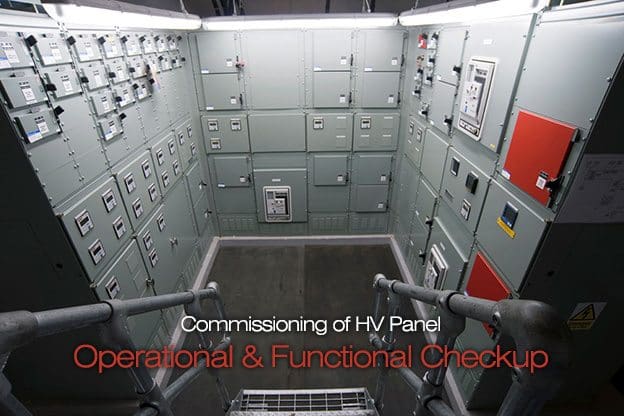
    Commissioning of HV Panel – Operational and Functional Checkup

    $
    0
    0
    Commissioning of HV Panel - Operational and Functional Checkup

    Commissioning of HV Panel - Operational and Functional Checkup (on photo Macmillan – New High Voltage Panel by Skilz Building Solutions)

    Main Objective

    The main objective of the test is to check the proper operation function of the circuit breaker; in this test we do the following:


    A. Close Operation Test – Local—Remote

    This test is conducted by manual, Local and Remote.

    For the manual Operation test, we will charge the spring manual and breaker is also closed my manual and opening also done. For the Local operation we give Control supply and A.C supply for spring charge motor.

    We close the Circuit Breaker using the TNC (Trip Neutral Control) switch.

    We observe for the closing coil function and spring charging of motor operation. For remote operating is the site is ready (such as plc or BMS) then remote operation is done using the remote system.

    If its site is not ready for this, we provide a local signal to the remote terminal and observe the operation of breaker.


    B. Trip Operation Test – Local-Remote

    This test is conducted by manual, Local and Remote. For the manual Operation test, The manually charged breaker is opened using the Trip switch.. For the Local operation we give Control supply and A.C supply for spring charge motor. We open the Breaker using the TNC switch.

    We observe for the tripping coil function. For remote operating is the site is ready (such as plc or BMS) then remote operation is done using the remote system.

    If its site is not ready for this, we provide a local signal to the remote terminal and observe the operation of breaker.


    C. Protection Trip

    For this test the breaker has in closed position at initially. We provide an auxiliary rated voltage to Master trip relay, and observe the opening of the breaker and the position of the trip coil.

    Functional Check

    1. Emergency Trip

    For this test the breaker has to be in charged or ON position, we operate the emergency push button. We observe the operation of circuit breaker opening.


    2. Aux. Switch Operation

    When the breaker is in open condition we check the Aux. contact of the breaker using continuity tester, to conform the contact is in NO /NC. Then we close the Circuit Breaker and check the same contact with continuity tester, to conform the contact is in NC /NO.


    3. On-Off Indications (Lamp + Flag)

    When the breaker is in open condition we check the Lamp + Flag of the relay. Then we close the Circuit Breaker and check the same Lamp operation.


    4. Trip / Trip circuit healthy Lamp Indication

    The relay is operated and we observer the Trip lamp indication.


    5. Limit Switch for spring charge motor

    On this test we observe the operation of the limit switch of the spring charging motor.

    We give an A.C power to motor and observer the operation of motor and charging of spring, on the indication of fully charged spring the motor operation has to get stopped.


    6. Test / Service Limit Switch

    This test is conducted to check the Test / Service Limit Switch Operation. During rack out the Breaker we obverse the indicator to change to test position and during rack in the breaker we obverse the indicator to change to service.


    7. Operation Counter

    This test is conducted if operational counter provision is available in breaker. We operated the breaker and look for the change in counter for counting the operation.


    8. Heater / Heater Switch / Thermostat

    The control A.C supply is given for heater and we look for heater operation.


    9. Function of illumination and socket switch

    In this test we look for the panel internal illumination and socket switch operation. We operate the limit switch manually and observe the operation of illumination circuit.

    Reference: Commissioning of HT electrical system – Sterling & Wilson Ltd.

    Talking About HV Shunt Reactor Switching (part 1)

    $
    0
    0
    Talking About HV Shunt Reactor Switching

    Talking About HV Shunt Reactor Switching (photo by Zaporozhtransformator Joint Stock Company - ZTR)

    Content

    1. Scope
    2. Shunt reactors application
    3. Closing operation
    4. Opening operation (in next part)
    5. Conclusions (in next part)

    Scope

    These notes aim to give basic idea of the main criticalities related to HV shunt reactor switching, particularly in terms of voltage, and how such problems are faced and solved by modern switching technology.

    Go to Content ↑


    Shunt reactors application

    Three-phase shunt reactors are basically aimed to compensate excess of reactive power generation so preventing unacceptable voltage rise and power losses.

    Lightly loaded1, long power transmission lines over 220kV, or cables 100kV and higher, are capacitive loads causing voltage increase because of the line charging currents flowing through the line / cable self inductance (Ferranti effect).

    In this cases the reactor is switched on and off during the day depending on the load, only. In fact, due to the need of reactive power consumption for voltage control and electrical system safety, the shunt reactor should be never tripped: in case of reactor fault, the whole line is tripped.

    1 As a reference value, it should be considered as “light” a load less than 70% of the surge impedance loading (SIL). For instance, a 345kV line with surge impedence 350Ω has about 3452/350 = 340MW SIL.

    That is consistent with the fact that in some EHV lines permanently under-loaded, fixed reactors are installed (provided just with a disconnecting switch in presence of redundant shunt reactors, for maintenance purposes).

    Another example of shunt reactor application is in presence of filter banks acting as capacitors at power frequency: that is the typical situation of HVDC converter station. HVDC converters produce harmonic distortion that need proper filter design to avoid heavy impact on network power quality.

    Different combination of filters could be are foreseen in different load conditions to get the target value of THD. At the same time filters’ capacitor banks act also as a reactive power source providing the needed Mvar to the converter, which is an important inductive load.

    Sometimes it could happen that specific combinations of converter load and filters configuration can satisfy the harmonic constraints, but lead to the reactive power generated by filters exceeding that consumed by converter over acceptable level: in that situations a shunt reactor is used.

    The configuration of shunt reactors may be various (bank of single-phase reactors, three-phase unit with a 3- or 5-legged core, etc.) , but following considerations still remain valid.

    It is to be noted that shunt reactor is, by definition, a reactor directly connected to the network; in some applications reactors are applied through a transformer (e.g. connected to tertiary winding); in both cases the principle is the same and the reactor acts as a linear inductance2 , but this paper refers to the first.

    On the other hand, despite the different possible earthing methods (isolated, solidly earthed or earthed through neutral reactor), solidly earthed three-phase shunt reactors will be considered.

    2 In case of iron core reactors, linearity is obtained with integrated air gaps.


    Go to Content ↑


    Closing operation

    For what concerns the closing operation, the shunt reactor can be simply modeled as an inductance in series with a resistance. The latter is always present, despite the effort to minimize losses.

    Shunt reactor closing operation scheme

    Shunt reactor closing operation scheme


    Energy stored in the inductor before circuit breaker closing is zero, and network voltage is:

    Network voltage

    The current flowing in the circuit is then:

    The current flowing in the circuit

    Where:

    Shunt reactor closing operation formulae


    The way to cancel the transient term is to close the circuit breaker when the steady state component of current is zero (γ = φ). More simply, suppose and resistive part of the reactor impedance be zero (φ = 90°): the transient part of current is zero if the circuit breaker is switched on when the voltage
    reaches its maximum value (γ = 90°).

    On the contrary, the transient term will be maximum if the circuit breaker closes with γ = φ ±90°. In the simplified example that means γ = 0.

    As the two terms (transient and steady state) sum each other, half a cycle later, when they have the same sign, the current increases over the steady state maximum value. The actual value depends on the circuit damping. Very low damping circuits (it is almost the case of shunt reactors) can see a current doubled, compared with the steady state.

    In three phase circuits, with three-pole operated circuit breakers it is quite easy to meet a critical closing instant on at least one phase.

    Because of above mentioned asymmetry in the transient current trend, closing operation can also generate zero sequence currents.

    Despite of the linear design of shunt reactors, in case of their switching in at the worst instant (phase voltage equal to zero), the flux will increase with the voltage-time-area during the first half-cycle to a value twice the maximum flux in normal operation.

    The current is proportional to the flux density, until reactor core saturation occurs. Above the point of saturation the current will increase faster than the flux. Saturation will be present in different amount in the three phases, because of the three-phases voltage 120° displacement.

    That means the sum of DC components in the three phase currents will not be null, so producing a zero sequence current which could lead to nuisance tripping by protections.

    The way to mitigate the high inrush currents and generally, the switching transients, due to random closing instants is to control the making instant for each pole of the circuit breaker. That means a single-pole operated circuit breaker is needed together with a Controlled Switching Device (CSD).

    Several manufacturers offer their own models of CSD: basically the principle is the same and it is based on the measuring of voltage upstream the circuit breaker, on the source side.

    In several cases a current feedback signal is used for adaptation control: as the switching times can be affected by temperature, auxiliary voltage variations, mechanical contingencies, etc. a deviation from target instant can occur. Such deviation is detected and properly taken into consideration during the next operation.

    Go to Content ↑

    Will be continued in 2 days… stay in tune.

    Bibliography
    1. “Live Tank CB Application Guide” – ABB
    2. “Buyers Guide HV Live Tank Circuit Breakers Ed5 en” – ABB
    3. “Trasmissione e distribuzione dell’energia elettrica” – N. Faletti, P. Chizzolini
    4. “Switching Shunt Reactors” – Roy W Alexander, NeilA. McCord P.E.
    5. “HV shunt reactor secrets for protection engineers”- Zoran Gajić, Birger Hillström, Fahrudin Mekić

    Talking About HV Shunt Reactor Switching (part 2)

    $
    0
    0
    Power transformer shunt reactor

    Power transformer shunt reactor (on photo shunt reactor of Hyosung Power & Industrial Systems via DirectIndustry.com)


    Continued from first part: Talking About HV Shunt Reactor Switching (part 1)


    Content

    1. Scope (explained in previous part)
    2. Shunt reactors application (explained in previous part)
    3. Closing operation (explained in previous part)
    4. Opening operation
    5. Conclusions

    Opening operation

    In the case of shunt reactors the current to be interrupted are very low (typically less than few hundreds amperes) compared with the breaking capability of the circuit breakers: they are often referred to as “small inductive currents”.

    After opening of the circuit breaker, the current flows through the arc between the contacts. This arc is stable at high currents, but in the case of small inductive currents it is not and it is very common that the current is interrupted prior to the natural current zero (current chopping).

    The resulting chopping overvoltage (also called suppression overvoltage), and particularly overvoltages due to subsequent re-ignitions, may be a concern. These overvoltages take origin from the electromagnetic energy stored in the reactor inductance at the instant of chopping.

    The following picture shows a single-phase model of the system in subject, complete enough for the purposes of this paper.

    Single-phase model of the system

    Single-phase model of the system


    Upstream the circuit breaker, the source side is represented by a sinusoidal voltage source:

    Sinusoidal voltage source

    being U the rated voltage of the system, including the reactor. Inductance and capacitance to ground of the source side of the system are represented by Ls and Cs respectively. The parallel capacitance Cp is a parameter of the circuit breaker. Normally Cs >> Cp. The reactor is represented by its inductance L, the stray capacitance CL and the inductance of its connections up to the circuit breaker Lb.

    Even if not shown, both connections and reactor have their resistive part producing the damping effect which will be evident in the plot of current / voltage.

    If the current interruption occurs at the passage for zero value of current, then CL is charged at the max voltage (being current lagged approximately 90° from voltage):

    Stray capacitance formulae

    The parallel circuit CL // L starts oscillating at frequency Frequency formulae  and voltage does never exceeds the maximum system voltage.

    Suppose the chopped current is Ich ≠ 0. The electrostatic energy stored in the capacitances is the same than in the previous case. But, additionally, electromagnetic energy is stored in the inductance:

    Electromagnetic energy stored in the inductance

    The overall energy will swing forth and back in the following circuit:

    El. circuit


    Inductance Lb is negligible, and Cs>> Cp let us replace the series connected capacitance with Cp only. So inductance L is now in parallel with capacitance (Cp+ CL). The energy stored in the circuit is now:

    Energy stored in the circuit

    The suppression peak overvoltage is reached as soon as the whole energy charges the capacitance (Cp+ CL):

    suppression peak overvoltage

    It can be shown that for air blast, oil and SF6 circuit breakers, the chopping current is proportional to the square root of total capacitance seen from the circuit breaker terminals. In the circuit in subject that is given by the parallel of Cp with the series of Cs and CL.

    In the hypothesis that Cs >> CL it can be written:

    Chopping current

    Where N is the number of interrupting chambers per pole. Chopping number λ is a characteristic of the circuit breaker and can be assumed to be a constant for different types of circuit breakers, except for vacuum circuit breakers.

    Typical ranges of chopping numbers are:

    Circuit breaker typeChopping number (λ)
    (AF0.5
    Minimum oil7 – 10 x 104
    Air blast15 – 24 x 104
    SF64 – 17 x 104

    Considering that L formulae, expression (1) can be written in p.u. of max voltage Max voltage formulae:

    Max voltage formulae

    Recovery voltage peak

    Recovery voltage peak


    The resonance frequency on reactor side is now Resonance frequency on reactor side (about 1÷5kHz).

    On source side, with a sufficiently extended network Ls and Cs are high enough to say that there are negligible overvoltages and no oscillation: the network voltage can be assumed to stay constant at Network voltage.

    When the oscillating voltage on reactor reaches the opposite peak (after half a cycle), the consequent peak recovery voltage could exceed the dielectric withstand capability not yet fully recovered, so leading to reignition. A re-ignition will generate high-frequency transients, typically hundreds of kHz, in both the reactor voltage and the current through the circuit breaker.

    In fact during re-ignition the oscillating circuit is given by:

    Oscillating circuit

    Oscillating circuit


    The two capacitances discharge one on each other through the small inductance of connections with a frequency Frequency formulae. Several consecutive ignition can occur, for the same reasons:

    Supply and load side voltage

    Supply and load side voltage


    The interval between succeeding re-ignitions increases as a consequence of the progressively increased withstand capability of the insulating medium, each time able to withstand major recovery voltages.

    The difference between source and load side voltages immediately before each re-ignition increases time by time and so the overshoots when re-ignition occurs. But the potential danger for the reactor actually comes from the steep voltage transient that is imposed on the reactor at each voltage breakdown associated to a re-ignition.

    In fact steep front voltages may be unevenly distributed across the reactor winding, stressing the entrance turns in particular with high interturn overvoltages with consequent risk of winding insulation puncture.

    The steepness is determined only by the frequency of the second parallel oscillation circuit, which in its turn depends on the circuit layout.

    Differently, the first suppression overvoltage is associated with relatively low frequencies, so the relevant voltage stress is evenly distributed and is somehow more acceptable.

    Shunt reactors are normally protected by surge arresters, which will limit overvoltages to earth to acceptable levels. But arresters cannot reduce the steepness of the voltage swings associated with re-ignitions. Actually the way to effectively limit voltage stresses on reactors passes through avoiding re-ignition.

    Go to Content ↑

    Conclusions

    The target to reduce electrical stress and avoid harmful transients can be achieved by adopting the following measures:

    Controlled opening device,

    ensuring contacts separation early before current zero, so maximizing the arcing time and eliminating risk of re-ignition3; in addition to that, controlled closing can also be implemented to minimize inrush and zero sequence currents during energizing of shunt reactor; the controlled switching devices available on the market nowadays can perform both opening and closing controlled switching, which is a benefit for the reactor as well as the circuit breaker (maintenance intervals minimized);

    Single-pole operated circuit breakers,

    suitable forused with controlled switching devices. Mechanical endurance class M2 and electrical endurance class E2 are recommended, especially for frequently switched reactors (which is the case of shunt reactors associated to renewable power plants or to HVDC converters).

    3 Contacts are not parted close to the instant of maximum phase-to-earth voltage, corresponding to the minimum of current, as one could expect, but around the instant when voltage is zero.

    In this way the current is high enough to produce stable arc for a sufficient time letting the gap between contacts be large when the low current will be chopped. An optimal arcing time is in the range 4-7 ms.

    Go to Content ↑

    Bibliography
    1. “Live Tank CB Application Guide” – ABB
    2. “Buyers Guide HV Live Tank Circuit Breakers Ed5 en” – ABB
    3. “Trasmissione e distribuzione dell’energia elettrica” – N. Faletti, P. Chizzolini
    4. “Switching Shunt Reactors” – Roy W Alexander, NeilA. McCord P.E.
    5. “HV shunt reactor secrets for protection engineers”- Zoran Gajić, Birger Hillström, Fahrudin Mekić

    What’s Really Important When You’re Designing The Low Voltage Switchgear?

    $
    0
    0
    What's Really Important When You're Designing The Low Voltage Switchgear?

    What's Really Important When You're Designing The Low Voltage Switchgear?

    Requirements on the Switchgear

    Here what’s important when you’re designing the low voltage switchgear:

    1. Device Application in the Supply Circuit
    2. Short-circuit strength
    3. Release (Trip Unit)
    4. Device Application in Supply Circuits (Coupling)
    5. Device Application in the Distribution Circuit
    6. Device Application in the Final Circuit

    1. Device Application in the Supply Circuit

    The system infeed is the most “sensitive” circuit in the entire power distribution. A failure here would result in the entire network and therefore the building or production being without power. This worst-case scenario must be considered during the planning.

    Redundant system supplies and selective protection setting are important preconditions for a safe network configuration. The selection of the correct protective devices is therefore of elementary importance in order to create these preconditions.

    Some of the key dimensioning data is addressed in the following:

    1.1 Rated current

    3WL11 air circuit breaker optimized for use in power distribution boards and wind turbines

    3WL11 air circuit breaker optimized for use in power distribution boards and wind turbines


    The feeder circuit-breaker in the Low-voltage main distribution (LVMD) must be dimensioned for the maximum load of the transformer/generator. When using ventilated transformers, the higher operating current of up to 1.5 x IN of the transformer must be taken into account.

    Go back to Index ↑


    2. Short-circuit strength

    The short-circuit strength of the feeder circuit-breaker is determined by (n–1) x Ik max of the transformer or transformers (n = number of transformers).

    This means that the maximum shortcircuit current that occurs at the installation position must be known in order to specify the appropriate short-circuit strength of the protective device (Icu).

    Circuit breaker nameplate

    Circuit breaker nameplate


    2.1 Utilization category

    When dimensioning a selective network, time grading of the protective devices is essential. When using time grading up to 500 ms, the selected circuit-breaker must be able to carry the short-circuit current that occurs for the set time. Close to the transformer, the currents are very high.

    This current carrying capacity is specified by the Icw value (rated short-time withstand current) of the circuit-breaker. This means the contact system must be able to carry the maximum short-circuit current, i.e. the energy contained therein, until the circuit-breaker is tripped.

    This requirement is satisfied by circuit-breakers of utilization category B (e.g. air circuit-breakers, ACB). Current-limiting circuit breakers (molded-case circuit breakers, MCCB) trip during the current rise. They can therefore be constructed more compactly.

    Go back to Index ↑


    3. The Release (Trip Unit)

    For a selective network design, the release (trip unit) of the feeder circuit-breaker must have an LSI (electronic trip unit) characteristic.

    LSI (electronic protection unit)

    LSI (electronic protection unit)


    It must be possible to deactivate the instantaneous release (I).

    Depending on the curve characteristic of the upstream and downstream protective devices, the characteristics of the feeder circuit breaker in the overload range (L) and also in the time-lag short circuit range (S) should be optionally switchable (I4t or I2t characteristic curve).

    This facilitates the adaptation of upstream and downstream devices.

    3.1 Internal accessories

    Depending on the respective control, not only shunt releases (previously: f releases), but also undervoltage releases are required.

    3.2 Communication

    Information about the current operating states, maintenance, error messages and analyses, etc. is being increasingly required, especially from the very sensitive supply circuits. Flexibility may be required with regard to a later upgrade or retrofit to the desired type of data transmission.

    Go back to Index ↑


    4. Device Application in Supply Circuits (Coupling)

    If the coupling (connection of Network 1 to Network 2) is operated open, the circuit-breaker (tie breaker) only has the function of an isolator or main switch. A protective function (release) is not absolutely necessary.

    The following considerations apply to closed operation:

    4.1 Rated current

    Must be dimensioned for the maximum possible operating current (load compensation). The simultaneity factor can be assumed to be 0.9.

    4.2 Short-circuit strength

    The short-circuit strength of the feeder circuit-breaker is determined by the sum of the short-circuit components that flow through the coupling. This depends on the configuration of the component busbars and their supply.

    4.3 Utilization category

    As for the system supply, utilization category B is also required for the current carrying capacity (Icw value).

    4.4 Release

    Partial shutdown with the couplings must be taken into consideration for the supply reliability. As the coupling and the feeder circuit-breakers have the same current components when a fault occurs, similar to the parallel operation of two transformers, the LSI characteristic is required.

    The special “Zone Selective Interlocking (ZSI)” function should be used for larger networks and/or protection settings that are difficult to determine.

    Go back to Index ↑


    5. Device Application in the Distribution Circuit

    The distribution circuit receives power from the higher level (supply circuit) and feeds it to the next distribution level (final circuit).

    Depending on the country, local practices, etc., circuit-breakers and fuses can be used for system protection.

    The specifications for the circuit dimensioning must be fulfilled. The ACB has advantages if full selectivity is required. However for cost reasons, the ACB is only frequently used in the distribution circuit as of a rated current of 630 A or 800 A. As the ACB is not a current-limiting device, it differs greatly from other protective devices such as MCCB, MCB and fuses.

    As no clear recommendations can otherwise be given, Table 1 shows the major differences and limits of the respective protective devices.

    Go back to Index ↑


    6. Device Application in the Final Circuit

    The final circuit receives power from the distribution circuit and supplies it to the consumer (e.g. motor, lamp, non-stationary load (power outlet), etc.). The protective device must satisfy the requirements of the consumer to be protected by it.

    Note: All protection settings, comparison of characteristic curves, etc. always start with the load. This means that no protective devices are required with adjustable time grading in the final circuit.

    Go back to Index ↑


    Table 1 – Overview of the protective devices

    Overview of the protective devices

    Table 1 - Overview of the protective devices


    *) with ETU: No limitation / with TMTU: depends on cable length

    Go back to Index ↑

    Reference: Siemens Energy Sector – Power Engineering Guide Edition 7.0

    Purposes and Examples of Safety Interlocking Devices

    $
    0
    0
    Purposes and Examples of Safety Interlocking Devices

    Purposes and Examples of Safety Interlocking Devices (on photo: GENIMOD – GREINER switchgear suitable for all areas relating to the generation, distribution and application of electrical energy in a wide variety of industrial and building services management sectors)

    Purpose od interlocking

    Most switchboards and motor control centres are fitted with a variety of electrical and mechanical safety interlocking devices.

    Their purposes are to protect against for example:

    • Withdrawing the switching device while it is carrying load or fault current.
    • Prevent the switching mechanism from being inserted when it is in its ‘on’ state.
    • Opening of access doors or panels before setting the switching device in its ‘off’ state.
    • Gaining physical access by human operators while the main conductors and contacts are energised.
    • Gaining access to the busbars when the switching devices have been withdrawn.
    • To prevent earthing switches from being closed on to live circuits or busbars.
    • Incorrect electrical operation of a complex process system in which various external devices, motors, pumps, etc. are intimately related. For example a lubrication oil pump must be running before the main drive motor is started on a pump or compressor.
    Most of the above interlocks are mechanical latches, bolts and shutters.

    The last category is electrical functions using wired relays or electronic logic. Electrical interlocking is also used to ensure that certain closing and tripping functions take place in a particular sequence.


    Interlocking examples //

    The following examples are typical interlocking sequences:


    Energising a downstream switchboard

    Energising a downstream switchboard is done through a transformer or plain interconnector. The upstream switching device is closed first. The downstream device is then closed. If either trips on fault then the other may be caused to trip by auxiliary circuits and relays.


    Two-out-of-three paralleling

    ‘Two-out-of-three paralleling’ is a term used when a switchboard has two parallel feeders. It is the term given to a particular closing scheme applied to the two incoming and the busbar section circuit breaker. The feeders are usually transformers.

    The purpose of the scheme is to enable a no-break transfer of the feeders to take place, and to minimise the duration of a prospectively high fault level that may exist during the transfer.

    Auxiliary switches are fitted within the three circuit breakers to determine when all three are closed. As soon as the third circuit breaker is closed the fault level at the busbars will in most cases be too high, and a signal is then given to one of the circuit breakers to trip. A selector switch is sometimes used to choose which of the three will trip. Some installations use a timer relay to delay the automatic tripping action, and the time delay setting is typically 0.5 to 2.0 seconds.

    This scheme is not used for all dual feeder switchboards, but is common practice with low voltage switchboards.


    Two supplies switched in parallel

    Where a situation can arise that two supplies could be switched in parallel, then it is necessary to check that they are in synchronism and come from the same source, e.g. either side of an upstream switchboard. Checking can be arranged in one of two methods, or a combination of both
    methods.

    The first method uses auxiliary switches on the upstream circuit breakers, usually the busbar section circuit breakers.

    These auxiliary switches give a signal that its circuit breaker is open, thereby signalling that an unsynchronised supply will exist at the downstream location. The signal is used to prevent the three downstream circuit breakers being closed all at the same time, i.e. the ‘two-out-of-three paralleling’ scheme is inhibited from closing its third circuit breaker.

    The Mors Smitt MS2SY212 synchronism check relay

    The Mors Smitt MS2SY212 synchronism check relay is designed to measure the phase angle between the monitored single phase voltages on the line & bus sides of a circuit breaker & verify that this angle is less than setting


    The second method is popular and uses a ‘synchronising check’ relay (25) to sense the voltage on both sides of a circuit breaker. For the above mentioned dual incomer switchboard all three circuit breakers would be equipped with the synchronising check relays.


    Normal / Standby Mechanically Interlocked ACB’s

    Cant see this video? Click here to watch it on Youtube.

    Reference: Handbook of Electrical Engineering: For Practitioners in the Oil, Gas and Petrochemical Industry – Alan L. Sheldrake (Get it from Amazon)


    Location of Current Transformers in HV Substation

    $
    0
    0
    Siemens High Voltage Instrument Transformers

    Siemens High Voltage Instrument Transformers

    Power flow

    Current transformers are used for protection, instrumentation, metering and control. It is only the first function that has any bearing on the location of the current transformer.

    Ideally the current transformers should be on the power source side of the circuit breaker that is tripped by the protection so that the circuit breaker is included in the protective zone.

    In many circuits the power flow can be in either direction and it then becomes necessary to decide which location of fault is most important or likely and to locate the current transformers on the side of the circuit breaker remote from those faults. In the case of generator (and some transformer) circuits it is necessary to decide whether the protection is to protect against for faults in the generator or to protect the generator against system faults.

    Current transformers can often be located in the generator phase connections at the neutral end and will then protect the generator from the system faults and to a large degree give protection for faults in the generator.

    When current transformers can be accommodated within the circuit breaker, they can in most cases be accommodated on both sides of the circuit breaker and the allocation of the current transformers should give the desired overlapping of protective zones.

    With some designs of circuit breaker the current transformer accommodation may be on one side only and it may be necessary to consider the implications of the circuit breaker position in the substation before deciding on the electrical location of the current transformers.

    CT’s mounted inside the CB (CT’s on both sides of CB)

    CT’s mounted inside the CB (CT’s on both sides of CB)


    CT’s are on the circuit side of the CB

    CT’s are on the circuit side of the CB


    However the risk of a fault between the current transformers and the circuit breaker and within the circuit breaker itself is very small and so the economics of accommodating the current transformers may have an important influence on their location.

    Where separate current transformer accommodation has to be provided, the cost of separately mounted current transformers and also the extra substation space required almost always results in them being located only on one side of the circuit breaker. In practice this is generally on the circuit side of the circuit breaker.

    This follows metalclad switchgear practice where this is the easiest place to find accommodation, and is also the optimum position when bus zone protection is required.

    Often it may be possible to accommodate current transformers on the power transformer bushings or on through wall bushings. When this is done it is usually for economic reasons to save the cost of, and space for, separately mounted current transformers.

    Transformer mounted current transformers have minor disadvantages in that a longer length of conductor and, more especially, the bushing is outside the protected zone, and in the event of the transformer being removed then disconnections have to be made to the protective circuits.

    Note that the arrangement of the individual current transformers within a unit should preferably be arranged that any protective zones overlap and that current transformers for other functions are included within the protected zone.

    Under by-pass conditions (where this is provided) the circuit is switched by the bus coupler circuit breaker.

    The location of the current transformers is determined by whether the protective relaying and current transformers are provided by the bus coupler circuit, or whether the protective relaying and current transformers of the circuit are used with the tripping signal being routed to the bus coupler circuit breaker during by-pass. If the latter method is used then the current transformers must be separately mounted on the line side of the by-pass isolator.

    Advantages

    The advantage of this method is that the circuit protection is unchanged to the possibly inferior protection of the bus coupler circuit. On the other hand the circuit would have to be taken out of service to work on the current transformers.

    The need for continued metering of the by-passed circuit needs also to be considered.


    Possible locations of current transformers

    Figures 1 (a), (b) and (c) show possible locations of current transformers in a portion of mesh substation.


    Arrangement (a)

    In arrangement (a) the current transformers are summed to equate to the feeder current and to operate the circuit protection.

    Mesh Circuit CT’s - Arrangement (a)

    Mesh Circuit CT’s – Arrangement (a)


    The protection also covers a portion of the mesh and, with overlapping current transformers as shown, the whole mesh is included in discriminative protective zones. Because the feeder current may be significantly smaller than the possible mesh current, the ratio of the mesh current transformers may be too high to give the best feeder protection.


    Arrangement (b)

    In arrangement (b) the current transformers are in the feeder circuit and so their ratio can be chosen to give the best protection.

    Mesh Circuit CT’s - Arrangement (b)

    Mesh Circuit CT’s – Arrangement (b)


    However there is now no discriminative protection for the mesh. Note that the current  transformers can be located either inboard or outboard of the feeder isolator, the choice being dependent on the ease of shutting down the feeder circuit and the undesirability of opening the mesh if maintenance of the current transformer were required.


    Arrangement (c)

    The arrangement shown in (c) is a combination of (a) and (b) with, if necessary, different ratio current transformers in the feeder circuit. This arrangement however requires three sets of current transformers as opposed to two and one in arrangements (a)and (b).

    Mesh Circuit CT’s - Arrangement (c)

    Mesh Circuit CT’s – Arrangement (c)


    Similar arrangements are possible with breaker-and-a-half substations with the slight difference that at the end of the diameter the protection becomes protection for the busbar instead of a feeder. All the diameter currents are summed for the bus zone protection.

    Reference: Substation design/application guide – V AYADURAI BSC, C.Eng, FIEE Engineering Expert

    An Example of Choosing 138 kV Line Circuit Breaker

    $
    0
    0
    An Example of Choosing 138 kV Line Circuit Breaker

    An Example of Choosing 138 kV Line Circuit Breaker (photo credit: wilsonconst.com)

    Let’s choose 138 kV line #3 circuit breaker

    To better understand a process of high voltage equipment selection, let’s discuss an example of choosing 138 kV Line #3 Circuit Breaker, shown in Figure 1, assuming that the following information about the system is available:

    Power System for Example of 138 kV Breaker Selection

    Figure 1 – Power System for Example of 138 kV Breaker Selection


    Continuous current for all the lines:

    • Line #1 – 1,000 A,
    • Line #2 – 1,500 A,
    • Line #3 – 800A

    3-phase fault current on the bus is 46.5 kA, contributions from the lines:

    • Line #1 – 24.5 kA,
    • Line#2 – 12kA,
    • Line#3 – 10kA

    Projected Substation load growth is 25%.

    Available breaker ratings:

    • Continuous current: 1,200 A, 2,000 A, 3,000 A
    • Short circuit interrupting capability: 40 kA, 50 kA

    Let’s see the solution…

    Future load considering 25% growth: (1000 A + 1500 A – 800 A) x 1.25 = 2,125 A.

    This load may be fed from Line #3 through its circuit breaker if lines #1 and #2 are switched off. So, the breaker should be sized to carry at least 2,125 A. Closest available continuous rating meeting this requirement is 3,000 A.

    Maximum 3-phase fault current that Line #3 breaker needs to interrupt may be calculated by deducting from a total bus fault current a contribution from line #3, i.e. 46.5 – 10 = 36.5 kA

    Closest short circuit current interrupting rating and meeting requirement to be at least 36.5 kA is 40 kA.

    This is a summary of the selected circuit breaker ratings:

    • Rated maximum voltage – 138 kV
    • Rated continuous current – 3,000 A
    • BIL – 650 kV
    • Rated short circuit current – 40 kA
    As you can see, selection of equipment for a specific application requires an input data which may be obtained from system studies. Such data include power flows, load projection, short circuit current calculations, etc., which are usually performed by utility company planners.

    Reference: Fundamentals of Modern Electrical Substations (Part 3: Electrical Substation Engineering Aspects) – Boris Shvartsberg, Ph.D., P.E., P.M.P.

    5 Most Common Critical Power Distribution Topologies

    $
    0
    0
    5 Most Common Critical Power Distribution Topologies

    5 Most Common Critical Power Distribution Topologies (photo credit: crown-electric.com)

    Today’s mission-critical applications

    In many of today’s mission-critical applications, ever-increasing reliability requirements are the norm. A critical part of this reliability is the reliability of the electric power distribution system for a given facility.

    Among the most demanding applications is that of a data center, where the enduse equipment cannot tolerate even a momentary power outage and, further, even relatively minor disturbances in the power system can cause computer systems to re-boot, causing operational down-time.

    A full-scale utility failure, lasting for minutes or even hours, is therefore not tolerable for these types of systems. In fact, even the approximately10 seconds of outage required for transfer of the system to generator power is not an option in these types of systems, a concept that will be explored in greater depth below.

    That no power system component can operate with 100% reliability is a well-known fact. Another fact is that the availability of utility power is less than 100% (typically 99-99.9%).

    Therefore, the possibility of utility power and internal system component failure must be taken into account in the system design.


    Topologies

    The choice of power system distribution topology is the first line of defense against critical-load outages.

    1. Secondary-Selective ‘Main-Tie-Main’ Arrangement
    2. Main-Tie-Main’ topology
    3. Ring Bus Arrangement
    4. Primary Loop Arrangement
    5. Composite Primary Loop/Secondary Selective Arrangement

    1. Secondary-Selective ‘Main-Tie-Main’ Arrangement

    In the context of automatic transfers, the most common arrangement is the secondary selective or “main-tie-main” arrangement. One implementation of this arrangement is as shown in Figure 1:

    Secondary-Selective 'Main-Tie-Main' Arrangement

    Figure 1 – Secondary-Selective ‘Main-Tie-Main’ Arrangement


    In this arrangement, there are two busses, each of which serves approximately 50% of the load, but is sized to carry the entire load. In Figure 1, this means that each transformer, secondary main circuit breaker, and secondary equipment bus is sized to carry the entire load.

    Should a transformer fail, the entire load may be transferred to the other transformer and its associated secondary bus via the bus tie circuit breaker.

    Go back to Topologies ↑


    2. Main-Tie-Main’ topology

    There are many variations on previous arrangement. In critical-power applications the most common variation is to use two bus tie circuit breakers, and have the two secondary busses separated into two different pieces of equipment. Another variation is the main-main arrangement, which omits the bus tie circuit breaker and simply has the two secondary busses connected all the time.

    In this arrangement, one power source normally carriesthe entire load, and the other is strictly a standby power source should the normal source fail. In this way the main-main arrangement is analogous to an automatic transfer switch (ATS).

    Both of these variations are shown in Figure 2.

    Variations on the 'Main-Tie-Main' topology a.) 'Main-Tie-Tie-Main' b.) 'Main-Main'

    Figure 2 – Variations on the ‘Main-Tie-Main’ topology a.) ‘Main-Tie-Tie-Main’ b.) ‘Main-Main’


    Other arrangements exist, however none are as popular in the critical-power distribution environment as the secondary-selective “main-tie-main” and its variants.

    It should be noted that the main-tie-main topology is also commonly used at the medium-voltage level.

    Go back to Topologies ↑


    3. Ring Bus Arrangement

    One other arrangement, however, has been used with great success is the ring bus, as illustrated in Figure 3:

    Ring Bus Arrangement

    Figure 3 – Ring Bus Arrangement


    The ring bus arrangement allows the flexibility of supplying multiple loads using multiple busses. It is most often used at the medium-voltage level, and usually in a “closed loop” arrangement with all of the bus tie circuit breakers closed.

    Go back to Topologies ↑


    4. Primary Loop Arrangement

    A variation on the ring-bus is the primary loop arrangement shown in Figure 4:

    Primary Loop Arrangement

    Figure 4 – Primary Loop Arrangement


    A primary loop arrangement typically uses load-interrupter switches for switching on the loop, and is more economically justifiable than a full ring-bus system. Typically, the loop is operated in an “open-loop” arrangement, but still gives the ability to supply all loads from either side of the loop.

    Go back to Topologies ↑


    5. Composite Primary Loop/Secondary Selective Arrangement

    Extreme flexibility and increased reliability are obtained by combining topologies. An example of this is the composite primary loop/secondary-selective arrangement shown in Figure 5.

    Here, multiple failure contingencies are addressed ina generally economically-feasible manner.

    Composite Primary Loop/Secondary Selective Arrangement

    Figure 5 – Composite Primary Loop/Secondary Selective Arrangement


    Go back to Topologies ↑

    Reference: Critical-Power Automatic Transfer Systems – Design and Application / Bill Brown, P.E., Jay Guditis, Square D Critical Power Competency Center

    Rating Definitions Applied to Medium Voltage Circuit Breaker

    $
    0
    0
    Rating Definitions Applied to Medium Voltage Circuit Breaker

    Rating Definitions Applied to Medium Voltage Circuit Breaker (on photo: SQUARE D medium voltage circuit breaker 15kV 1200A)

    MV protection applications

    The medium voltage circuit breaker is the device of choice when sophisticated system protection at the medium voltage level is required. Most modern medium voltage circuit breakers use a vacuum as the interrupting means, although sulfur-hexafluoride (SF6) based units still exist and in use.

    Medium voltage circuit breakers are generally not equipped with integral trip units as low voltage circuit breakers are. Instead, protective relays must be used to sense abnormal conditions and trip the circuit breaker accordingly.

    Most modern medium voltage circuit breakers are rated on a symmetrical current basis. The following rating definitions apply:


    Rated Maximum Voltage - The highest RMS phase-to-phase voltage for which the circuit breaker is designed.

    Rated Power Frequency - The frequency at which the circuit breaker is designed to operate.

    Rated Dry Withstand VoltageThe RMS voltage that the circuit breaker in new condition is capable of withstanding for 1 minute under specified conditions.

    Rated Wet Withstand Voltage - The RMS voltage that an outdoor circuit breaker or external components in new condition are capable of withstanding for 10s.

    Rated Lightning Impulse Withstand VoltageThe peak value of a standard 1.2 x 50µ s wave, as defined in IEEE Std 4-1978, that a circuit breaker in new condition is capable of withstanding.

    Rated Continuous CurrentThe current in RMS symmetrical amperes that the circuit breaker is designed to carry continuously.

    Rated Interrupting TimeThe maximum permissible interval between the energizing of the trip circuit at rated control voltage and the interruption of the current in the main circuit in all poles.

    Rated Short Circuit Current (Required Symmetrical Interrupting Capability)The value of the symmetrical component of the short-circuit current in RMS amperes at the instant of arcing contact separation that the circuit breaker shall be required to interrupt at a specified operating voltage, on the standard operating duty cycle, and with a DC component of less than 20% of the current value of the symmetrical component.

    Required Asymmetrical Interrupting CapabilityThe value of the total RMS short-circuit current at the instant of arcing contact separation that the circuit breaker shall be required to interrupt at a specified operating voltage and on the standard operating duty cycle.

    This is based upon a standard time constant of 45ms (X/R ratio =17 for 60 Hz and 14 for 50 Hz systems) and an assumed relay operating time of _ cycle.


    Rated closing and latching capability - The circuit breaker shall be capable of closing and latching any power frequency making current whose maximum peak is equal to or less than 2.6 (for 60 Hz power frequency; 2.5 for 50 Hz power frequency) times the rated short-circuit current.

    Rated Short-Time CurrentThe maximum short-circuit current that the circuit breaker can carry without tripping for a specified period of time.

    Maximum Permissible Tripping DelayThe maximum delay time for protective relaying to trip the circuit breaker during short-circuit conditions, based upon the rated short-time current and short-time current-carrying time period.

    Rated Transient Recovery Voltage (TRV)At its rated maximum voltage, a circuit breaker is capable of interrupting three-phase grounded and ungrounded terminal faults at the rated short-circuit current in any circuit in which the TRV does not exceed the rated TRV envelope.

    For a circuit breaker rated below 100kV, the rated TRV is represented by a 1-cosine wave, with a magnitude and time-to-peak dependent upon the rated maximum voltage of the circuit breaker.

    Rated Voltage Range Factor KFactor by which the rated maximum voltage may be divided to determine the minimum voltage for which the interrupting rating varies linearly with the interrupting rating at the rated maximum voltage by the following formula:

    Ivop = Iv max · (Vmax / Vop)

    where:

    • Iv max - is the rated short-circuit current at the maximum operating voltage
    • Vmax - is the rated maximum operating voltage
    • Vop - is the operating voltage where Vop ≥ (Vmax / K)
    • Ivop - is the short-circuit current interrupting capability where Ivop ≤ Iv max · K

    For values of Vop below (Vmax÷ K) the short-circuit interrupting capability was considered to be equal to (Iv max · K). This model was more representative of older technologies such as air-blast interruption.

    Because most modern circuit breakers employ vacuum technology, the current version assumes that K = 1., which gives the same short circuit rating for all voltages below the rated voltage. However, in practice designs with K > 1 still exist and are in common use.


    Table 1: Preferred ratings for indoor circuit breakers with K=1.0

    Preferred ratings for indoor circuit breakers with K=1.0

    Preferred ratings for indoor circuit breakers with K=1.0


    It should be noted that although 83 ms or 5 cycles is the “preferred” value for the rated interrupting time, 3-cycle designs are common.

    Table 2:
    Preferred ratings for indoor circuit breakers with voltage range factor K > 1.0

    Table 2: Preferred ratings for indoor circuit breakers with voltage range factor K > 1.0

    Table 2: Preferred ratings for indoor circuit breakers with voltage range factor K > 1.0

    Few more words about MV CBs…

    Medium voltage circuit breakers are typically provided without integral trip units. For this reason, custom protection must be provide via protective relays.

    Circuit breakers are equipped with tripping and closing coils to allow tripping and closing operations via protective relays, manual control switches, PLC’s, SCADA systems, etc.

    The circuit breaker internal control circuitry is arranged per IEEE C37.11-1997. Circuit breakers are also equipped with a number of auxiliary contacts to allow interlocking and external indication of breaker position.

    For medium voltage protection applications, circuit breakers offer flexibility that cannot be obtained with fuses. Further, they do not require a separate switching device as fuses do.

    These benefits are gained at a price

    Circuit breaker applications are more expensive than fuse applications, both due to the inherent cost of the circuit breakers themselves and due to the protective relays required. For many applications, however, circuit breakers are the only choice that offers the flexibility required.

    Large medium voltage services and distribution systems and most applications involving medium voltage generation employ circuit breakers.

    Reference: System Protection – Bill Brown, P.E., Square D Engineering Services

    Rating Definitions Applied to Low Voltage Molded-Case Circuit Breaker (MCCB)

    $
    0
    0
    Rating Definitions Applied to Low Voltage Molded-Case Circuit Breaker (MCCB)

    Rating Definitions Applied to Low Voltage Molded-Case Circuit Breaker (MCCB)

    For system protection 600V and below

    The molded-case circuit breaker is the “workhorse” for system protection 600V and below. A circuit breaker is a device designed to open and close by nonautomatic means and to open the circuit automatically on a predetermined overcurrent without damage to itself when properly applied within its rating.

    The following terms apply to molded-case circuit breakers:


    Voltage - Circuit breakers are designed and marked with the maximum voltage at which they can be applied. Circuit breaker voltage ratings distinguish between delta-connected, 3-wire systems and wye-connected, 4-wire systems.

    As stated in NEC article 240.85, a circuit breaker with a straight voltage rating, such as 240 or 480 V can be used in a circuit in which the nominal voltage between any two conductors does not exceed the circuit breaker’s voltage rating.

    Breakers with slash ratings, such as 120/240 V or 480 Y/277 V, can be applied in a solidly-grounded circuit where the nominal voltage of any conductor to ground does not exceed the lower of the two values of the circuit breaker’s voltage rating and the nominal voltage between any two conductors does not exceed the higher value of the circuit breaker’s voltage rating.

    Frequency - Molded-case circuit breakers are normally suitable for 50Hz or 60Hz. Some have DC ratings as well.

    Continuous current or Rated current - This is the maximum current a circuit breaker can carry continuously at a given ambient temperature rating without tripping (typically 40˚C).

    In accordance with NEC article 210.20 a circuit breaker (or any branch circuit overcurrent device) should not be loaded to over 80% of its continuous current unless the assembly, including the circuit breaker and enclosure, is listed for operation at 100% of its rating.

    PolesThe number of poles is the number of ganged circuit breaker elements in a single housing. Circuit breakers are available with one, two, or three poles, and also four poles for certain applications.

    Per NEC article 240.85 a two-pole circuit breaker cannot be used for protecting a 3-phase, corner-grounded delta circuit unless the circuit breaker is marked 1ø – 3ø to indicate such suitability.

    Control voltageThe control voltage rating is the AC or DC voltage designated to be applied to control devices intended to open or close a circuit breaker. In most cases this only applies to accessories that are custom-ordered, such as motor operators.


    Interrupting rating - This is the highest current at rated voltage that the circuit breaker is intended to interrupt under standard test conditions.

    Short-time or Withstand RatingThis characterizes the circuit-breaker’s ability to withstand the effects of short-circuit current flow for a stated period. Molded-case circuit breakers typically do not have a withstand rating, although some newer-design breakers do.

    Instantaneous overrideA function of an electronic trip circuit breaker that causes the instantaneous function to operate above a given level of current if the instantaneous function characteristic has been disabled.

    Current Limiting Circuit BreakerThis is a circuit breaker which does not employ a fusible element and, when operating in its current-limiting range, limits the let-through I2t to a value less than the I2t of a _-cycle wave of the symmetrical prospective current.

    HIDThis is a marking that indicates that a circuit breaker has passed additional endurance and temperature rise tests to assess its ability to be used as the regular switching device for high intensity discharge lighting. Per NEC 240.80 (D) a circuit breaker which is used as a switch in an HID lighting circuit must be marked as HID.

    HID circuit breakers can also be used as switches in fluorescent lighting circuits.

    SWDThis is a marking that indicates that a circuit breaker has passed additional endurance and temperature rise tests to assess its ability to be used as the regular switching device fluorescent lighting.

    Per NEC 240.80 (D) a circuit breaker which is used as a switch in an HID lighting circuit must be marked as SWD or HID.

    FrameThe term Frame is applied to a group of circuit breakers of similar configuration. Frame size is expressed in amperes and corresponds to the largest ampere rating available in that group.

    Thermal-magnetic circuit breakerThis type of circuit breaker contains a thermal element to trip the circuit breaker for overloads and a faster magnetic instantaneous element to trip the circuit breaker for short circuits.

    On many larger thermal-magnetic circuit breakers the instantaneous element is adjustable.

    Electronic trip circuit breakerAn electronic circuit breaker contains a solid-state adjustable trip unit. These circuit breakers are extremely flexible in coordination with other devices.

    SensorAn electronic-trip circuit breaker’s sensor is usually an air-core current transformer (CT) designed specifically to work with that circuit breaker’s trip unit.

    The sensor size, in conjunction with the rating plug, determines the electronic-trip circuit breaker’s continuous current rating.

    Rating plugAn electronic trip circuit breaker’s rating plug can vary the circuit breaker’s continuous current rating as a function of it’s sensor size.

    Typical molded-case circuit breakers are shown in Figure 1, where on the left is a thermal-magnetic circuit breaker, and on the right is an electronic-trip circuit breaker. The thermal-magnetic circuit breaker is designed for cable connections and the electronic circuit breaker is designed for bus connections, but neither type is inherently suited for one connection type over another.

    Circuit breakers may be mounted in stand-alone enclosures, in switchboards, or in panelboards.

    Molded-Case circuit breakers

    Figure 1 – Molded-Case circuit breakers

    Thermal-magnetic circuit breaker time-current characteristic

    A typical thermal-magnetic circuit breaker time-current characteristic is shown in figure 2.

    Note the two distinct parts of the characteristic curve: The thermal or long-time characteristic is used for overload protection and the magnetic or instantaneous characteristic is used for short-circuit protection.

    Note also that there is a band of operating times for a given fault current. The lower boundary represents the lowest possible trip time and the upper boundary represents the highest possible trip time for a given current.

    Thermal magnetic circuit breaker time-current characteristic

    Figure 2 – Thermal magnetic circuit breaker time-current characteristic

    Electronic-trip circuit breaker time-current characteristic

    The time-current characteristic for an electronic-trip circuit breaker is shown in figure 3. The characteristic for an electronic trip circuit breaker consists of the long time pickup, long-time delay, short-time pickup, short time delay, and instantaneous pickup parameters, all of which are adjustable over a given range.

    This adjustability makes the electronic-trip circuit breaker very flexible when coordinating with other devices. The adjustable parameters for an electronic trip circuit breaker are features of the trip unit.

    In many cases the trip unit is also available without the short-time function.

    In catalog data the long-time characteristic is listed as L, the short-time is listed as S, and the instantaneous as I. Therefore an LSI trip unit has long-time, short-time, and instantaneous characteristics, whereas an LI trip unit has only the long-time and instantaneous characteristics.

    For circuit breakers that have a short-time rating, the instantaneous feature may be disabled, enhancing coordination with downstream devices.

    Electronic-trip circuit breaker time-current characteristic

    Figure 3 – Electronic-trip circuit breaker time-current characteristic


    If the instantaneous feature has been disabled one must still be cognizant of any instantaneous override feature the breaker has, which will engage the instantaneous function above a given level of current even if it has been disabled in order to protect the circuit breaker from damage.


    Coordination

    Typical coordination between an electronic and a thermal magnetic circuit breaker is shown in figure 4 below. Because the time bands do not overlap, these two devices are considered to be coordinated.

    Typical molded-case circuit breaker coordination

    Figure 4 – Typical molded-case circuit breaker coordination


    A further reduction in the let-through energy for a fault in the region between two electronic-trip circuit breakers can be accomplished through zone-selective interlocking. This consists of wiring the two trip units such that if the downstream circuit breaker senses the fault (typically this will be based upon the short-time pickup) it sends a restraining signalto the upstream circuit breaker.

    The upstream circuit breaker will then continue to time out as specified on its characteristic curve, tripping if the downstream device does not clear the fault.

    However, if the downstream device does not sense the fault and the upstream devices does, the upstream device will not have the restraining signal from the downstream device and will trip with no intentional delay.

    Example

    For example, if zone selective interlocking were present in the system of figure 4 and fault occurs on bus C circuit breaker B will sense the fault and send a restraining signal to circuit breaker A. Circuit breaker A is coordinated with circuit breaker B, so circuit breaker B will trip first.

    If circuit breaker B fails to clear the fault, circuit breaker A will time out on its time-current characteristic per figure 4 and trip. If the fault occurs at bus B, circuit breaker B will not detect the fault and thus will not send the restraining signal to circuit breaker A. Circuit breaker A will sense the fault and will trip with no intentional delay, which is faster than dictated by its time-current characteristic per figure 4.

    Care must be used when applying zone-selective interlocking where there are multiple sources of power and fault currents can flow in either direction through a circuit breaker.

    Table 1 shows typical characteristics of molded-case circuit breakers for commercial and industrial applications. This table is for reference only; when specifying circuit breakers manufacturer’s actual catalog data should be used.

    Frame Size (A)Number of
    Poles
    Interrupting Rating at AC voltage (kA, RMS symmetrical)
    120 V240 V277 V480 V600 V
    10011014
    16565
    100, 1502, 3181414
    2, 3652518
    2, 31006525
    225, 2502, 3252222
    2, 3652522
    2, 31006525
    400, 6002, 3423022
    2, 3656525
    2, 310035
    800, 10003423022
    655025
    20010065
    12003423022
    3655025
    320010065
    1600, 20003655042
    312510065
    3000, 4000310010085
    3200150100

    Note that the continuous current rating is set by the sensor and rating plug sizes for a given electronic-trip circuit breaker. This can be smaller than the frame size. As can be seen from table 1, more than one interrupting rating can be available for a given frame size.

    Current-limiting circuit breakers are also available. Coordination between two current-limiting circuit breakers when they are both operating in the current limiting range is typically determined by test.

    By definition, low voltage molded case circuit breakers are not maintainable devices. Failure of a component generally requires replacement of the entire circuit breaker unless the circuit breaker has been specifically designed for maintainability.

    Magnetic-only circuit breaker swhich have only magnetic tripping capability are available. These are often used as short-circuit protection for motor circuits. For this reason these are often referred to as motor circuit protectors.

    Reference: System Protection – Bill Brown, P.E., Square D Engineering Services
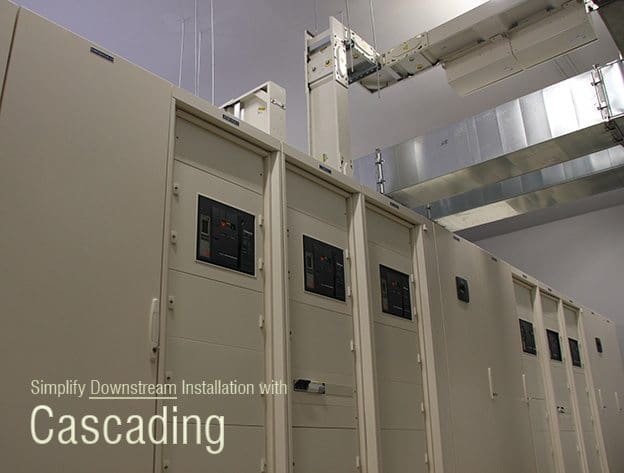
    Viewing all 150 articles
    Browse latest View live